Basic Experiments
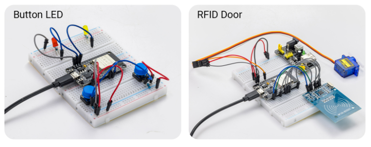
This introductory chapter guides you through the process of building fun, interactive devices—capable of visual, physical, and auditory responses—using a carefully selected range of common and engaging components such as LEDs, buzzers, buttons, and sensors. Through a series of hands-on experiments that progress from simple to complex, you will quickly familiarize yourself with hardware wiring, programming logic, and debugging techniques, rapidly transforming from a mere observer into a maker.
1. LED Blinking
In this experiment, you will learn how to control an LED using the ESP32 microcontroller. You will write a simple program to make the LED blink at regular intervals, introducing you to basic programming concepts and GPIO pin control.
Materials Needed:
ESP32 Development Board
LED
Resistor (220Ω)
Breadboard and Jumper Wires
Wiring Diagram:
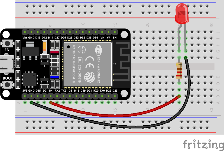
Wiring Table
No. |
Component |
Pin |
Connect to |
Note |
|---|---|---|---|---|
1 |
LED |
Anode (long leg) |
GPIO 4 |
series 220Ω |
1 |
LED |
Cathode (short leg) |
GND |
Example code:
// Define the LED connection pin
#define LED_PIN 4

void setup()
{
// Set GPIO4 to output mode
pinMode(LED_PIN, OUTPUT);
}

void loop()
{
// Turn on the LED
digitalWrite(LED_PIN, HIGH);

// Delay for 1 second
delay(1000);

// Turn off the LED
digitalWrite(LED_PIN, LOW);

// Delay for 1 second
delay(1000);
}
Display Effect:
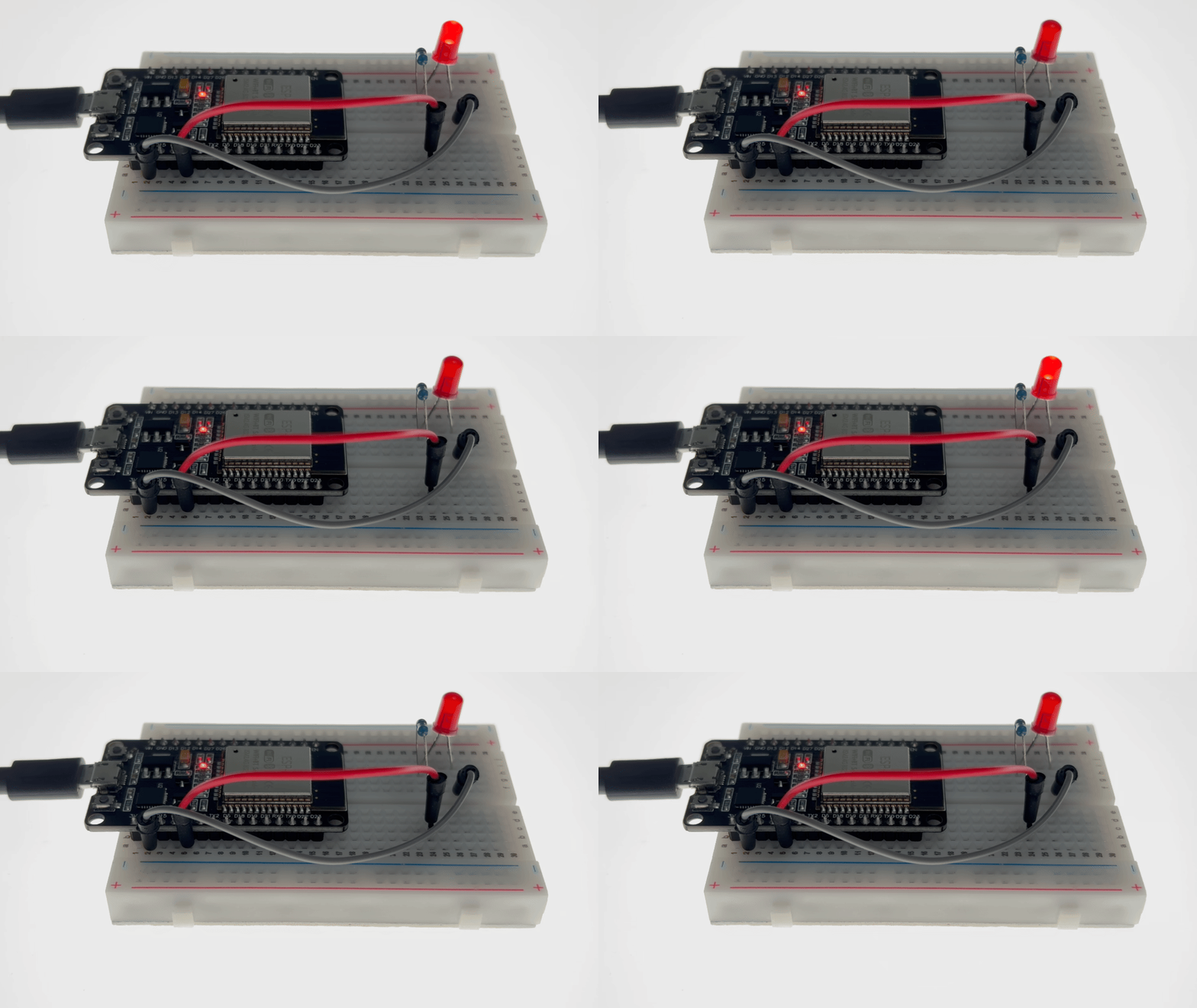
The LED light will continuously turn on and off at one-second intervals—lighting up, dimming, lighting up again, dimming again—creating a ceaseless breathing or flashing rhythm.
2. PWM LED
This experiment is a classic introductory project on analog signal acquisition and PWM output control. It aims to teach how to combine the ESP32’s ADC analog input with PWM pulse width modulation output to achieve stepless adjustment of light brightness using a physical knob.
Materials Needed:
ESP32 Development Board
LED
Potentiometer 10k
Breadboard and Jumper Wires
Wiring Diagram:
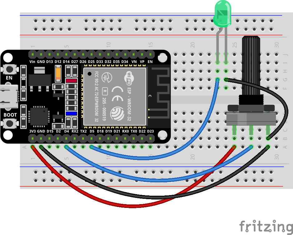
Wiring Table
No. |
Component |
Pin |
Connect to |
|---|---|---|---|
1 |
Potentiometer |
Right |
GND |
1 |
Potentiometer |
Middle (Wiper) |
GPIO 4 |
1 |
Potentiometer |
Left |
3.3V |
2 |
LED |
Anode (long leg) |
GPIO 5 |
2 |
LED |
Cathode (short leg) |
GND |
Example code:
// Potentiometer is connected to GPIO 4 (Analog ADC2_CH0)
const int potPin = 4;
// LED is connected to GPIO 5 (PWM capable)
const int ledPin = 5;

// variable for storing the potentiometer value
int potValue = 0;
// variable for storing the LED brightness
int brightness = 0;

void setup() {
  Serial.begin(115200);
  // Set LED pin as output
  pinMode(ledPin, OUTPUT);
  delay(1000);
}

void loop() {
  // Reading potentiometer value (0 - 4095 for ESP32 ADC)
  potValue = analogRead(potPin);

  // Map potentiometer value to LED brightness range (0 - 255)
  // PWM uses 8-bit resolution (0 = off, 255 = fully on)
  brightness = map(potValue, 0, 4095, 0, 255);

  // Set LED brightness via PWM
  analogWrite(ledPin, brightness);

  // Print both values to serial monitor
  Serial.print("Potentiometer: ");
  Serial.print(potValue);
  Serial.print(" -> LED Brightness: ");
  Serial.println(brightness);

  delay(50);  // Small delay for stable reading
}
Display Effect:
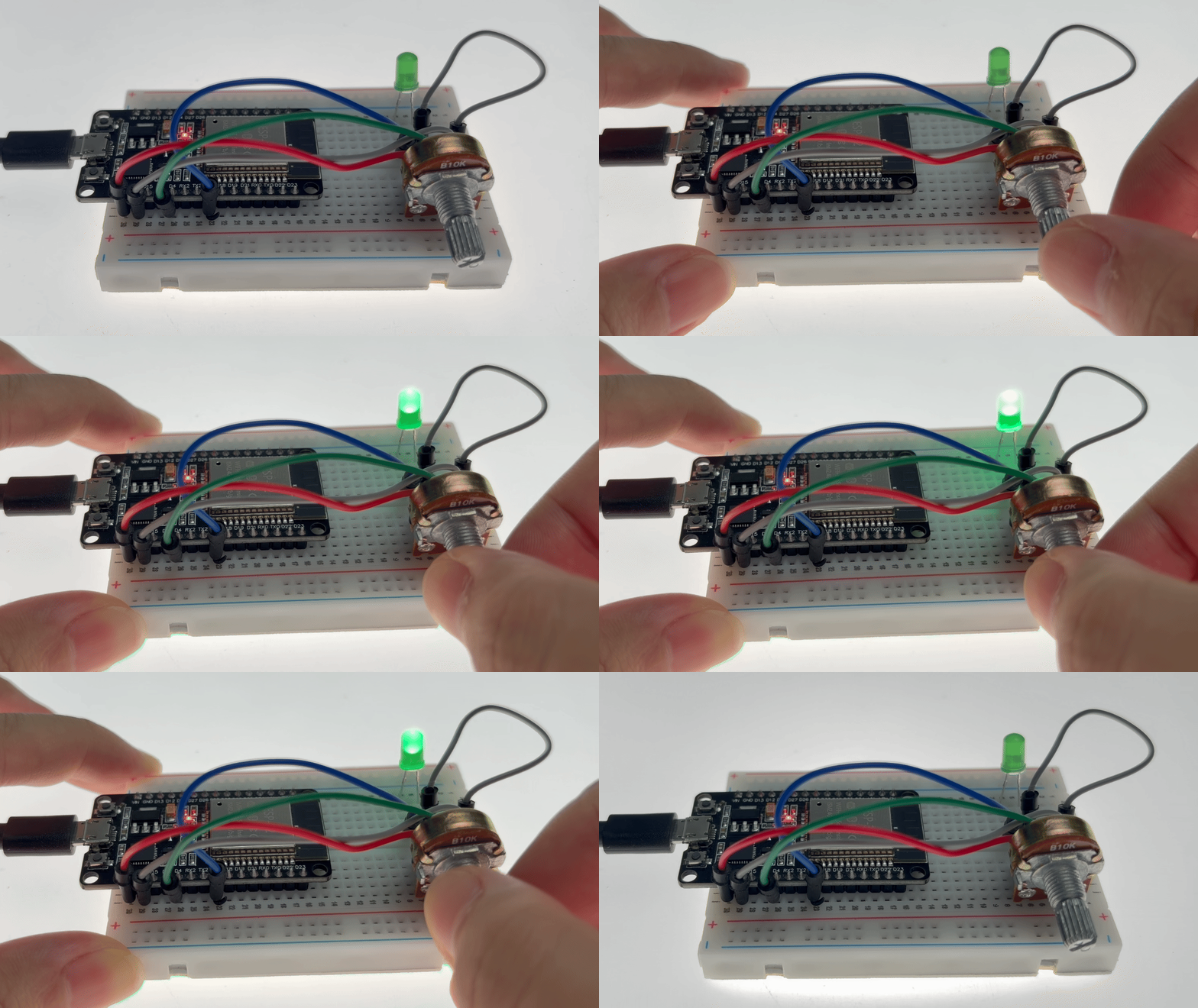
Rotating the potentiometer clockwise gradually brightens the LED until it reaches its brightest point.
Rotating the potentiometer counter-clockwise gradually dims the LED until it goes completely off.
3. Button LED
This experiment aims to teach two core programming techniques: key debouncing and state toggling. Two independent keys will control the on/off state of red and yellow LEDs respectively.
You will learn how to use `digitalRead()` to capture the rising edge trigger of a key (i.e., the instant it’s pressed) , and how to implement the logic of “state toggling once per press” using a state flag (bool variable) .
Simultaneously, simple software delay debouncing is incorporated into the code, allowing you to understand the signal jitter problem caused by mechanical keys at the instant they are pressed and its solution.
Materials Needed:
ESP32 Development Board
Button (2 PCS)
LED (Yellow、Red)
Resistor (220Ω、10KΩ)
Breadboard and Jumper Wires
Wiring Diagram:
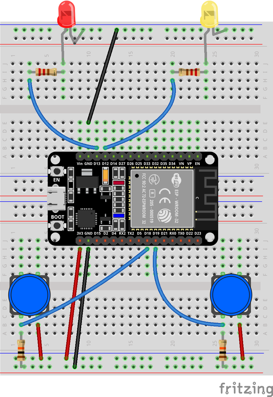
Wiring Table
No. |
Component |
Pin |
Connect to |
Note |
|---|---|---|---|---|
1 |
Red LED |
Anode (long leg) |
GPIO 13 |
series 220Ω |
1 |
Red LED |
Cathode (short leg) |
GND |
|
2 |
Yellow LED |
Anode (long leg) |
GPIO 12 |
series 220Ω |
2 |
Yellow LED |
Cathode (short leg) |
GND |
|
3 |
Button 1 |
Either pin |
3.3V |
|
3 |
Button 1 |
Other pin |
GPIO 18 |
with 10kΩ to GND |
4 |
Button 2 |
Either pin |
3.3V |
|
4 |
Button 2 |
Other pin |
GPIO 19 |
with 10kΩ to GND |
Example code:
Display Effect:
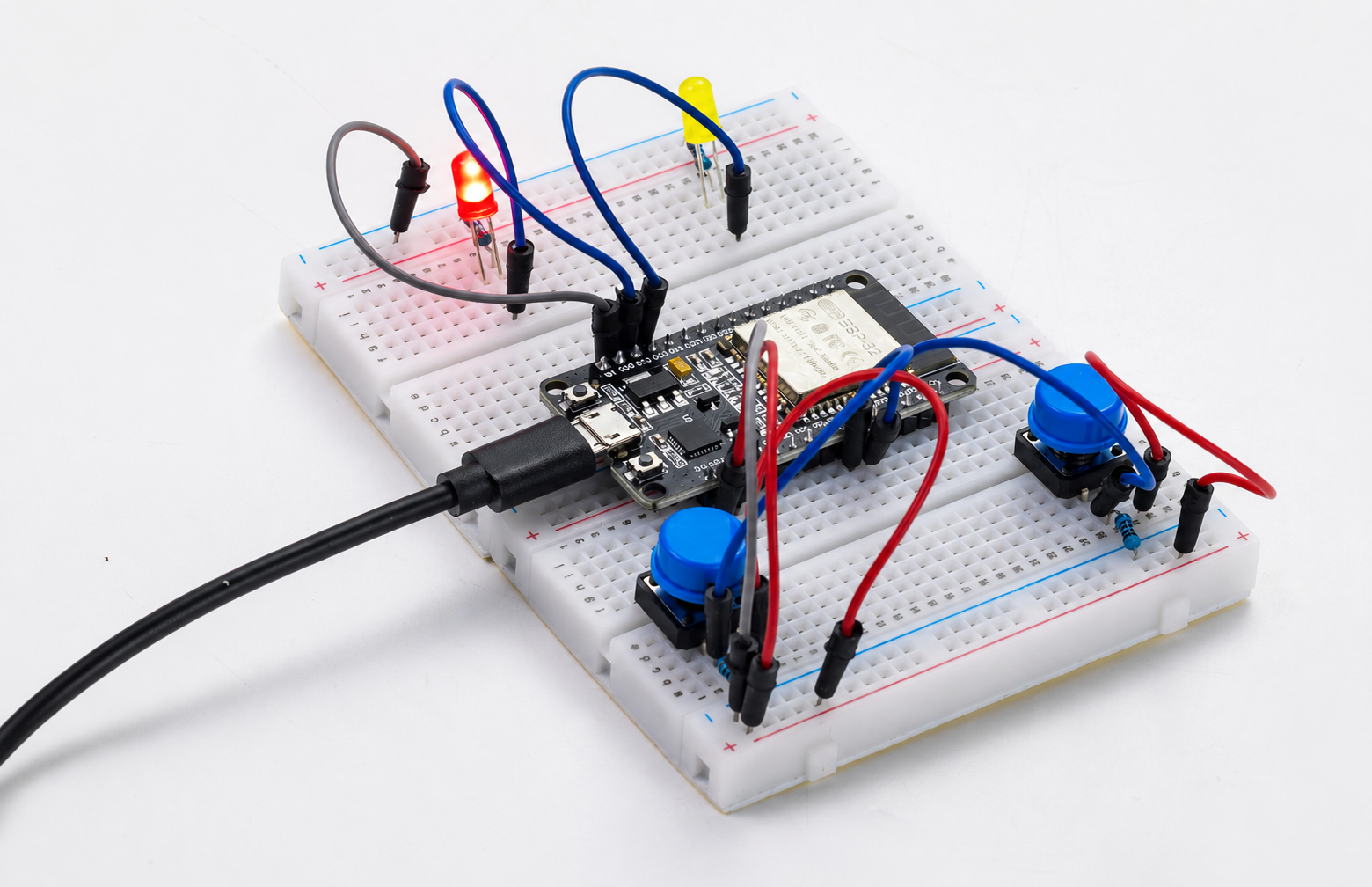
Pressing button 1 (GPIO18): The red LED’s state toggles—it turns on if currently off, and off if currently on, toggling each time it’s pressed.
Pressing button 2 (GPIO19): The yellow LED follows the same toggling logic, without interfering with each other.
4. Thermometer
This experiment is an advanced project on analog sensor signal acquisition and mathematical modeling. It aims to learn how to use the ESP32’s ADC to read the resistance changes of the NTC thermistor and accurately calculate the ambient temperature through a simplified version of the Steinhart-Hart equation (B value formula). You will master the following core skills:
Principle of NTC thermistor: Understand the characteristics of negative temperature coefficient resistance decreasing with increasing temperature, and master the application of B value formula
ADC high-precision sampling: using 12-bit resolution (0~4095) and 11dB attenuation, read the voltage value of the voltage divider circuit
Software filtering technology: Reduce noise interference and improve measurement stability through multiple sampling averages (20 times)
Voltage dividing circuit calculation: According to the series voltage dividing principle, the NTC current resistance value is deduced from the ADC voltage value.
Materials Needed:
ESP32 Development Board
Thermistor
Resistor (10K)
Breadboard and Jumper Wires
Wiring Diagram:
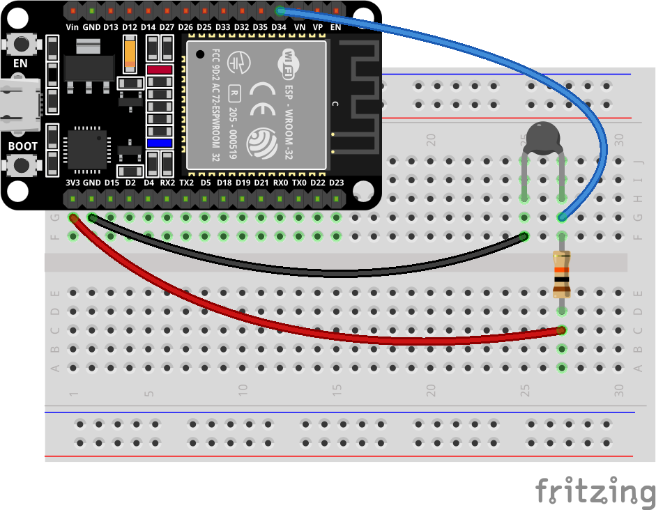
Wiring Table
No. |
Component |
Pin |
Connect to |
|---|---|---|---|
1 |
NTC Thermistor |
One pin |
GPIO 34 (ADC) |
1 |
NTC Thermistor |
Other pin |
GND |
2 |
10kΩ Resistor |
One pin |
3.3V |
2 |
10kΩ Resistor |
Other pin |
GPIO 34 (ADC) |
Example code:
Display Effect:
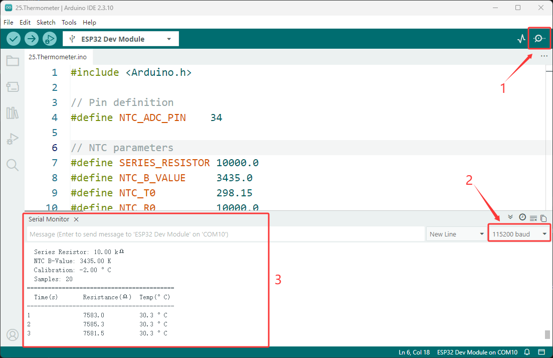
After burning the program, open the serial monitor (baud rate 115200), the system will display the NTC parameter information and header, and then automatically print the current time (seconds), NTC real-time resistance value (Ω) and temperature value every 1 second.
Pinch the NTC probe with your fingers or get close to the heat source, the resistance value will drop rapidly, the temperature value will rise simultaneously, and the response will be sensitive.
5. TEMP And HUMI Detection
This experiment is an introductory project on digital sensor driving and data acquisition, aiming to teach how to use ESP32 to read DHT11 temperature and humidity sensors and view environmental data in real time through a serial monitor.
Materials Needed:
ESP32 Development Board
DHT11 Sensor
Breadboard and Jumper Wires
Wiring Diagram:
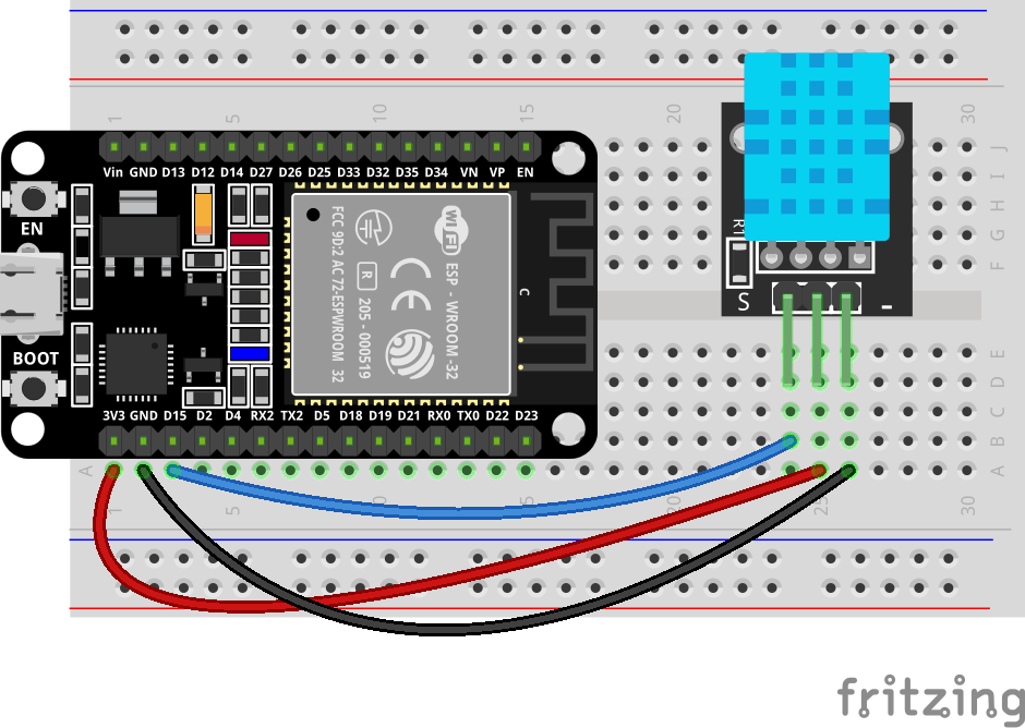
Wiring Table
No. |
Component |
Pin |
Connect to |
|---|---|---|---|
1 |
DHT11 Sensor |
VCC |
3.3V |
1 |
DHT11 Sensor |
GND |
GND |
1 |
DHT11 Sensor |
DATA |
GPIO 15 |
Example code:
Display Effect:
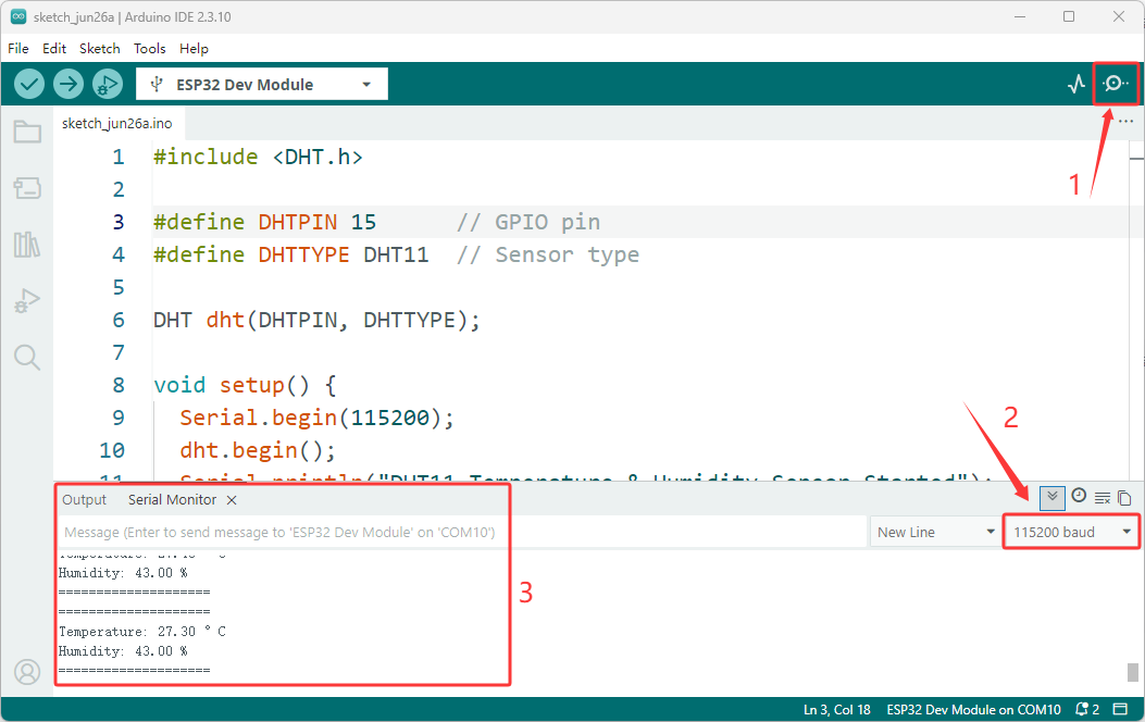
After programming, open the serial monitor (baud rate 115200). The system will automatically collect the current ambient temperature and humidity data every 2 seconds and print it out in a clear, separated format.
If the sensor connection is normal and the reading is successful, the current temperature and humidity values will be displayed.
6. Scan RFID
This experiment is an introductory project to RFID (Radio Frequency Identification) technology, aiming to teach you how to use the ESP32 and RC522 modules to read the unique identifier (UID) of RFID cards/tags. You will master the following core skills:
SPI Communication Protocol: Implement high-speed serial communication between the ESP32 and RC522 modules using the SPI.h library, and understand the collaborative operation of the SCK, MOSI, MISO, and SS pins.
MFRC522 Library Usage: Master the driving methods of RFID reader chips, including the complete process of initialization, card search, card reading, and sleep mode.
UID Data Parsing: Read the 4-byte (or 7-byte) unique identifier of the card and output it in hexadecimal format.
Materials Needed:
ESP32 Development Board
RC522 RFID Module
ID Card
Breadboard and Jumper Wires
Wiring Diagram:
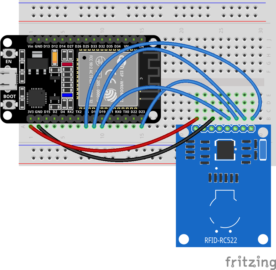
Wiring Table
No. |
Component |
Pin |
Connect to |
|---|---|---|---|
1 |
RC522 RFID Module |
VCC |
3.3V |
1 |
RC522 RFID Module |
GND |
GND |
1 |
RC522 RFID Module |
RST |
GPIO 4 |
1 |
RC522 RFID Module |
MISO |
GPIO 19 |
1 |
RC522 RFID Module |
MOSI |
GPIO 23 |
1 |
RC522 RFID Module |
SCK |
GPIO 18 |
1 |
RC522 RFID Module |
SDA (SS) |
GPIO 5 |
Example code:
Display Effect:
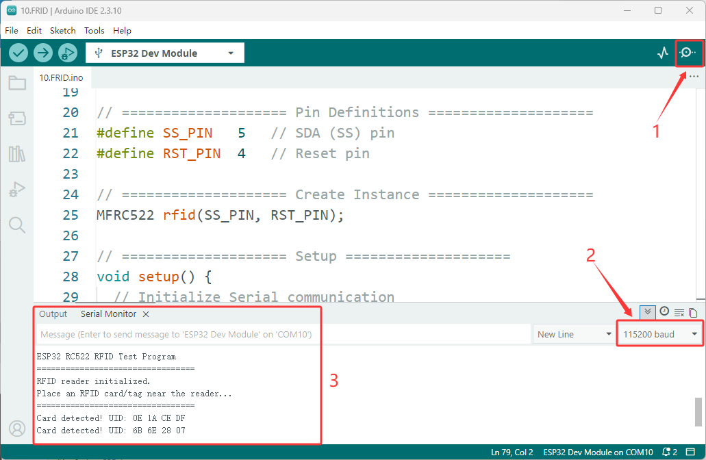
After programming and correctly connecting the RC522 module, open the serial monitor (baud rate 115200). The system will display a successful initialization message and wait for a card to approach.
When any RFID card or tag approaches the reader, the serial port will immediately output the card’s unique UID (hexadecimal format). After the card is removed, the system continues to wait for the next card to arrive, achieving continuous scanning and identification.
7. Music Player
This experiment is an introductory project for audio frequency generation and music programming. It aims to learn how to use the tone() function of ESP32 to drive a passive buzzer to play a melody.
Materials Needed:
ESP32 Development Board
Passive Buzzer
PN2222 Transistor
Resistor (1K)
Breadboard and Jumper Wires
Wiring Diagram:
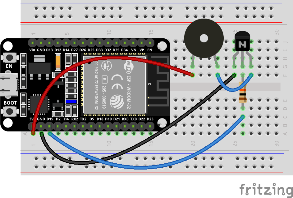
Wiring Table
No. |
Component |
Pin |
Connect to |
|---|---|---|---|
1 |
Passive Buzzer |
Positive (+) |
3.3V |
1 |
Passive Buzzer |
Negative (-) |
PN2222 Collector (C) |
2 |
PN2222 Transistor |
Emitter (E) |
GND |
2 |
PN2222 Transistor |
Base (B) |
1kΩ Resistor |
3 |
1kΩ Resistor |
One pin |
PN2222 Base (B) |
3 |
1kΩ Resistor |
Other pin |
GPIO 15 |
Example code:
Display Effect:
After burning the program, the passive buzzer will automatically play the classic nursery rhyme melody (Little Star) in a loop. Each note lasts 400ms, and there is a 10ms interval between notes to prevent sound adhesion. After playing it completely, pause for 2 seconds and then repeat, forming a continuous music loop.
8. Tilt Alarm
This experiment is a practical project applying embedded state machines. It aims to teach you how to detect device displacement using a tilt switch (ball switch) and build a complete security alarm system. You will master the following core skills:
Materials Needed:
ESP32 Development Board
Tilt switch
Button (1 PCS)
Active Buzzer
LED
Breadboard and Jumper Wires
Wiring Diagram:
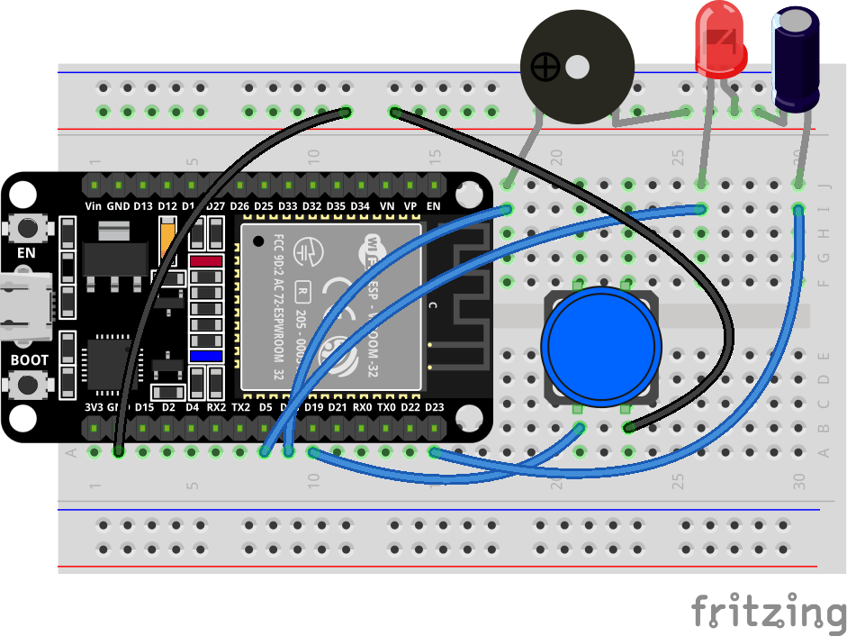
Wiring Table
No. |
Component |
Pin |
Connect to |
|---|---|---|---|
1 |
Tilt Switch |
One pin |
GPIO 23 |
1 |
Tilt Switch |
Other pin |
GND |
2 |
LED |
Anode (long leg) |
GPIO 5 |
2 |
LED |
Cathode (short leg) |
GND |
3 |
Active Buzzer |
Positive (+) |
GPIO 18 |
3 |
Active Buzzer |
Negative (-) |
GND |
4 |
Reset Button |
One pin |
GPIO 19 |
4 |
Reset Button |
Other pin |
GND |
Example code:
Display Effect:
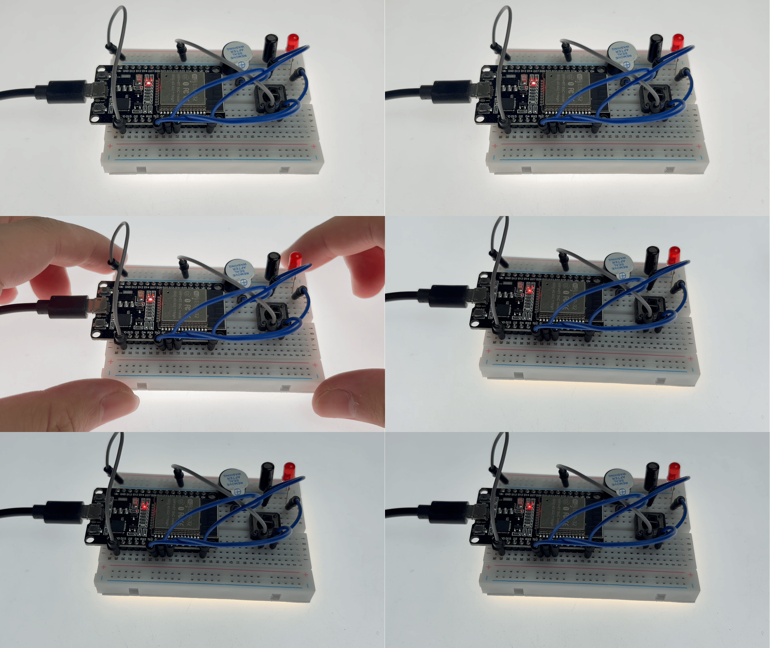
After the program is burned, the system automatically enters a 5-second arming countdown, during which the LED flashes rapidly. After the countdown ends, the system enters an alert state, the LED turns off, and the device remains stationary.
If the device tilts or moves, an alarm is immediately triggered. The LED flashes rapidly, the buzzer sounds continuously, and the alarm time is output via the serial port. Pressing the reset button clears the alarm, and the system re-enters the 5-second arming countdown.
9. 0.96 Inch Display
This experiment is an introductory project for OLED display and scrolling special effects. It aims to learn how to use ESP32 to drive the SSD1306 OLED screen and realize the horizontal scrolling animation effect of text. You will master the following core skills:
SSD1306 OLED driver: Initialize the OLED display of the I2C interface through the Adafruit_SSD1306 library and understand the configuration of the I2C address (0x3C/0x3D)
Display buffer operation: learn basic display functions such as clearDisplay() to clear the screen, setCursor() to position, println() to output text, etc.
Scroll effect control: Use startsscrollright() and startsscrollleft() to achieve smooth left and right scrolling of screen text, and stop scrolling through stopsscroll()
Scroll area setting: Understand the meaning of the row address parameters in startsscrollright(0x00, 0x0F) (0x00~0x0F is 16 lines in the full screen), and master the setting of the local scroll area
Serial port debugging: Output the initialization status through Serial.println() to facilitate troubleshooting hardware connection problems
Materials Needed:
ESP32 Development Board
0.96 Inch Display
Breadboard and Jumper Wires
Wiring Diagram:
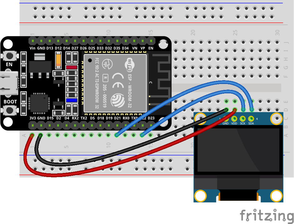
Wiring Table
No. |
Component |
Pin |
Connect to |
|---|---|---|---|
1 |
0.96 OLED |
VCC |
3.3V |
1 |
0.96 OLED |
GND |
GND |
1 |
0.96 OLED |
SCL |
GPIO 22 |
1 |
0.96 OLED |
SDA |
GPIO 21 |
Example code:
Display Effect:
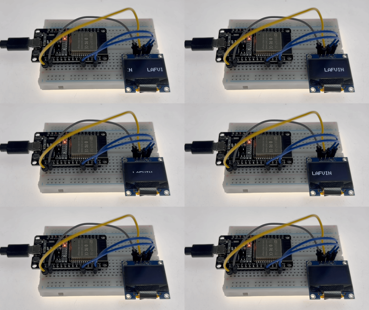
After the program is burned, the text LAFVIN is displayed in the center of the OLED screen (font size 2, approximately in the middle of the screen). After waiting for 2 seconds, the text starts to scroll to the right for 7 seconds, pauses for 1 second, then scrolls to the left for 7 seconds, pauses for 1 second, and so on, forming a dynamic display effect.
10. Keyboard Display
This experiment is a comprehensive project of human-computer interaction and multi-peripheral collaboration. It aims to learn how to combine a 4x4 matrix keyboard with an OLED display to build a real-time key display system. You will master the following core skills:
Matrix keyboard scanning principle: Understand the row and row scanning mechanism, detect key presses through row and row intersections, and save GPIO pin resources (4+4=8 pins control 16 keys)
Use of Keypad library: Master the configuration and calling of Keypad.h library, including key mapping, row and column pin definition, key detection and anti-shake processing
OLED display driver: Use the Adafruit_SSD1306 library to drive the OLED screen of the I2C interface, and learn operations such as display initialization, screen clearing, and text rendering.
Materials Needed:
ESP32 Development Board
4X4 Keyboard
0.96 Inch Display
Breadboard and Jumper Wires
Wiring Diagram:
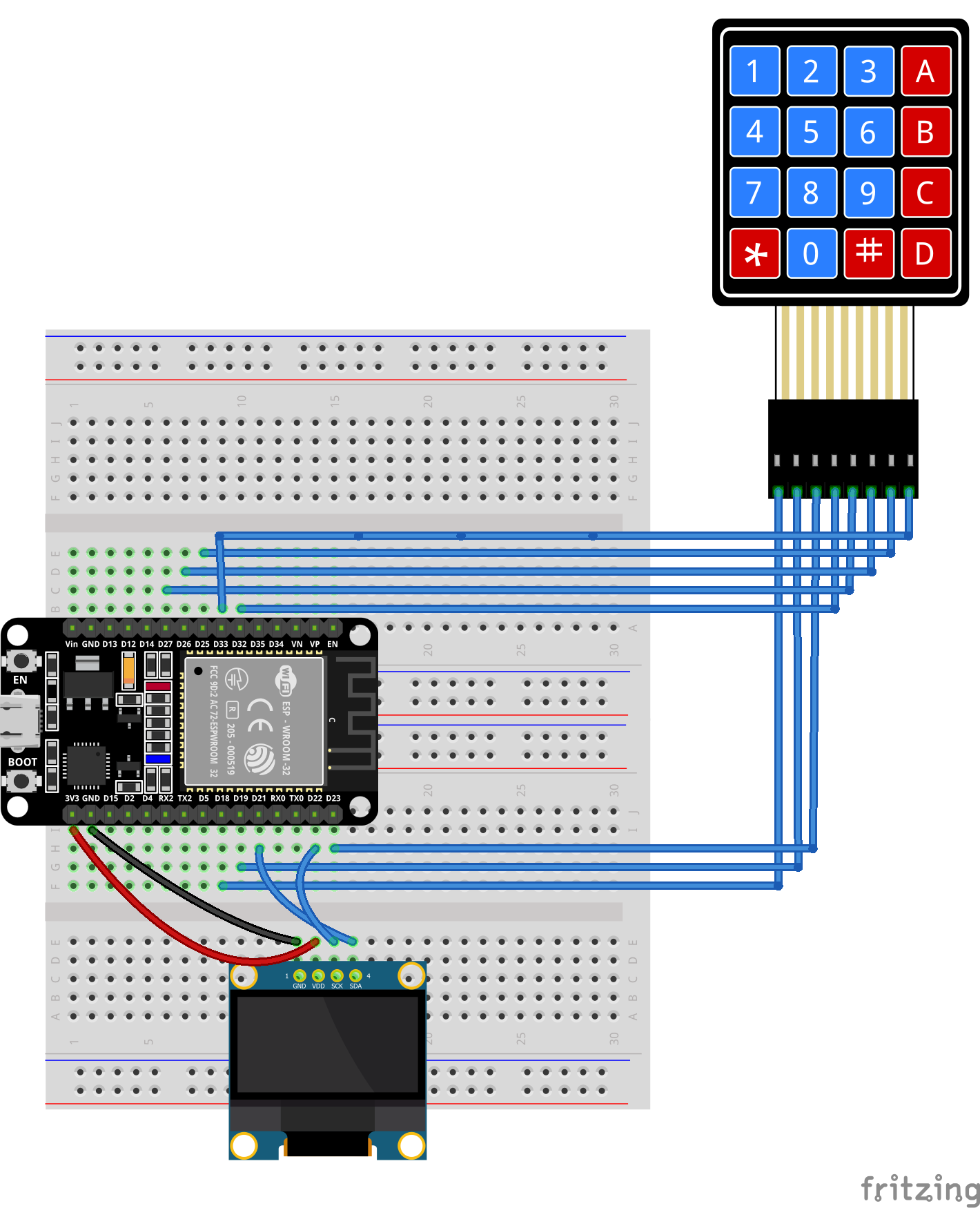
Wiring Table
No. |
Component |
Pin |
Connect to |
|---|---|---|---|
1 |
SSD1306 OLED |
VCC |
3.3V |
1 |
SSD1306 OLED |
GND |
GND |
1 |
SSD1306 OLED |
SCL |
GPIO 22 |
1 |
SSD1306 OLED |
SDA |
GPIO 21 |
2 |
Keypad Row 1 |
R1 |
GPIO 18 |
2 |
Keypad Row 2 |
R2 |
GPIO 19 |
2 |
Keypad Row 3 |
R3 |
GPIO 23 |
2 |
Keypad Row 4 |
R4 |
GPIO 32 |
3 |
Keypad Column 1 |
C1 |
GPIO 27 |
3 |
Keypad Column 2 |
C2 |
GPIO 26 |
3 |
Keypad Column 3 |
C3 |
GPIO 25 |
3 |
Keypad Column 4 |
C4 |
GPIO 33 |
Example code:
Display Effect:
The OLED screen first displays the startup prompt “Keypad Ready / Press any key”. The screen clears after 2 seconds and enters standby mode.
When any key of the matrix keyboard is pressed, the character of the key (0-9, A-D, *, #) will be displayed in real time in the center of the OLED screen in a large font (font size 4). The screen will remain unchanged after the key is released, and will be updated to the new character the next time a new key is pressed, achieving clear key visual feedback.
11. Human Body Detection
This experiment serves as an introductory project linking motion detection with an audio-visual alarm system. It aims to teach you how to use an ESP32 to read signals from a Passive Infrared (PIR) motion sensor and drive an active buzzer to trigger an alarm. You will master the following core skills:
PIR Motion Sensor Interfacing: Learn to read digital signals and understand the sensor’s output characteristics—specifically, high-level output (motion detected) versus low-level output (stationary).
Active Buzzer Control: Drive the buzzer directly via a digital output pin and understand the distinction between active buzzers (which have a built-in oscillator) and passive buzzers.
Non-blocking Timer Design: Use millis() for timing control to ensure the buzzer continues sounding for 3 seconds after motion ceases before turning off, thereby preventing false triggers and rapid on/off cycling.
State Machine Programming: Manage the buzzer’s state using an isBuzzerActive flag to implement the complete logic flow: “Trigger → Hold → Delayed Turn-off.”
Materials Needed:
ESP32 Development Board
PIR Motion Sensor
Active Buzzer
Breadboard and Jumper Wires
Wiring Diagram:
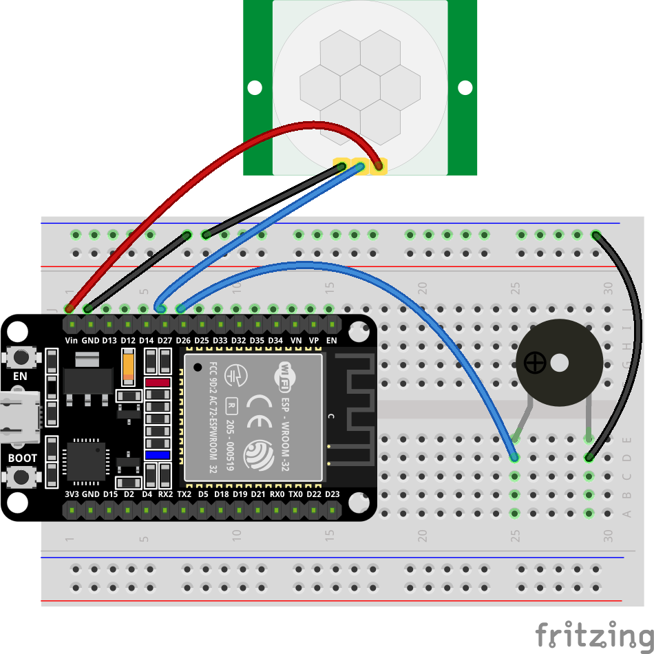
Wiring Table
No. |
Component |
Pin |
Connect to |
|---|---|---|---|
1 |
PIR Motion Sensor |
VCC |
5V |
1 |
PIR Motion Sensor |
GND |
GND |
1 |
PIR Motion Sensor |
OUT (Signal) |
GPIO 27 |
2 |
Active Buzzer |
Positive (+) |
GPIO 26 |
2 |
Active Buzzer |
Negative (-) |
GND |
Example code:
Display Effect:
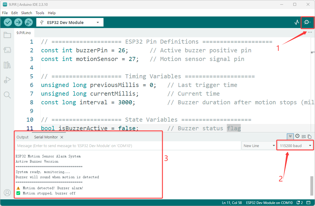
After the program is uploaded, the system enters monitoring mode.
When the PIR sensor detects human motion, the buzzer sounds immediately, and the serial port outputs the warning message “⚠️ Motion detected! Buzzer alarm!”.
The buzzer continues to sound as long as the motion persists, while the timer is continuously reset.
Once the motion stops, the buzzer remains active for another 3 seconds (to prevent frequent start-stop cycles caused by brief pauses) before automatically turning off; the serial port then outputs the message “✅ Motion stopped, buzzer off,” and the system returns to standby mode, awaiting the next trigger.
12. 7-Segment Display
This experiment serves as an introductory project for digital display and segment encoding, designed to teach you how to drive a 7-segment display using an ESP32 to cycle through the digits 0–9. You will master the following core skills:
7-Segment Display Principles: Understand the internal layout of the eight LED segments (a–g) and learn how to drive common-cathode and common-anode displays.
Segment Encoding and Truth Tables: Create a mapping table (2D array) of segment codes corresponding to digits 0–9 and understand the logic behind encoding these displays.
Arrays and Loop Control: Use an array (e.g., int segmentPins[]) to manage the seven pins and employ for loops for batch initialization and control.
LED Segment Control: Use digitalWrite() to control the on/off state of individual segments, combining them to form the desired numeric characters.
Materials Needed:
ESP32 Development Board
7-Segment Display
Breadboard and Jumper Wires
Wiring Diagram:
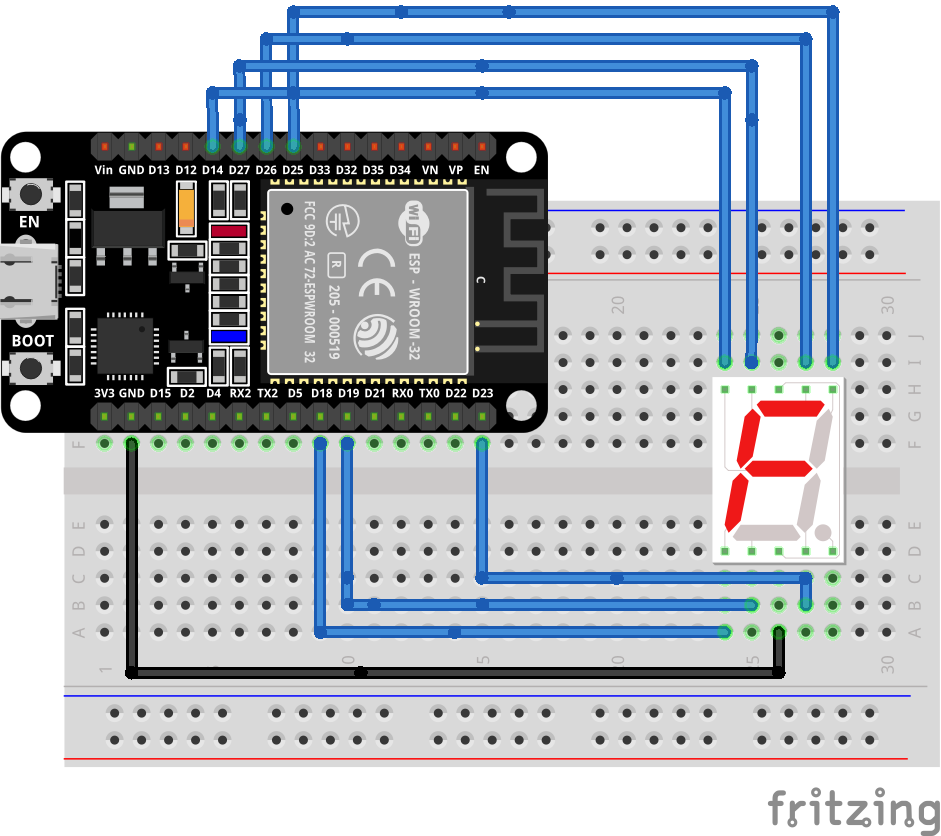
Wiring Table
No. |
Component |
Pin |
Connect to |
|---|---|---|---|
1 |
7-Segment Display |
a |
GPIO 26 |
1 |
7-Segment Display |
b |
GPIO 25 |
1 |
7-Segment Display |
c |
GPIO 23 |
1 |
7-Segment Display |
d |
GPIO 19 |
1 |
7-Segment Display |
e |
GPIO 18 |
1 |
7-Segment Display |
f |
GPIO 27 |
1 |
7-Segment Display |
g |
GPIO 14 |
1 |
7-Segment Display |
COM(-) |
GND |
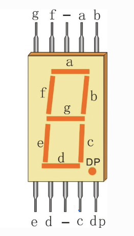
Example code:
Display Effect:
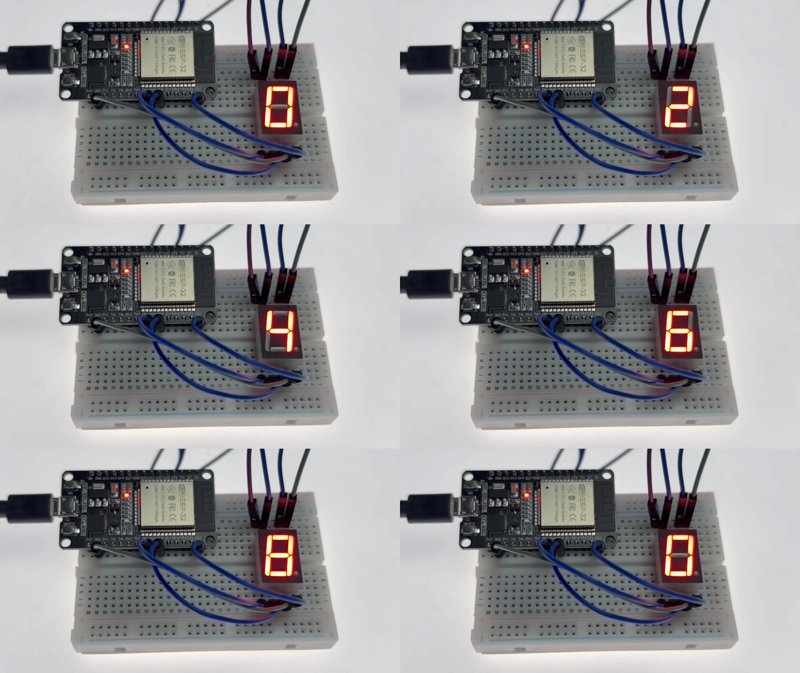
After the program is uploaded, the 7-segment display starts at 0 and increments by one digit every second, displaying up to 9 before returning to 0 to restart the cycle, creating a continuous “0-1-2-3-4-5-6-7-8-9-0-1…” display loop.
13. 4-Digit Counter
This experiment is a comprehensive project involving digital circuit expansion and dynamic scanning display. It aims to teach you how to use the 74HC595 shift register to expand GPIO capabilities for driving a 4-digit, 7-segment display and to control a counter using push-buttons. You will master the following core skills:
74HC595 Shift Register Driving: Understand the principle of serial-in/parallel-out operation, master the `shiftOut()` function for data transmission, and control 8 segment outputs using only 3 GPIO pins.
Dynamic Scanning Display: Utilize the human eye’s persistence of vision by rapidly cycling through the digit-select pins of the 4-digit display (switching digits every 1.5ms) to show multiple digits simultaneously, thereby conserving pin resources.
Common-Cathode Display Driving: Activate digits with a low-level signal and segments with a high-level signal; understand the driving differences between common-cathode and common-anode displays.
Button Debouncing: Implement non-blocking debouncing using `millis()` to accurately detect button presses and prevent false triggers caused by mechanical contact bounce.
BMC (Binary-to-Segment) Encoding: Use a hexadecimal segment code lookup table (e.g., 0x3F for the digit ‘0’) to efficiently store segment data for digits.
Multi-digit Decomposition Algorithm: Use division and modulo operations to split the counter value (0–9999) into thousands, hundreds, tens, and ones places for 4-digit display.
Materials Needed:
ESP32 Development Board
4-7-Segment Display
Button
74HC595
Breadboard and Jumper Wires
Wiring Diagram:
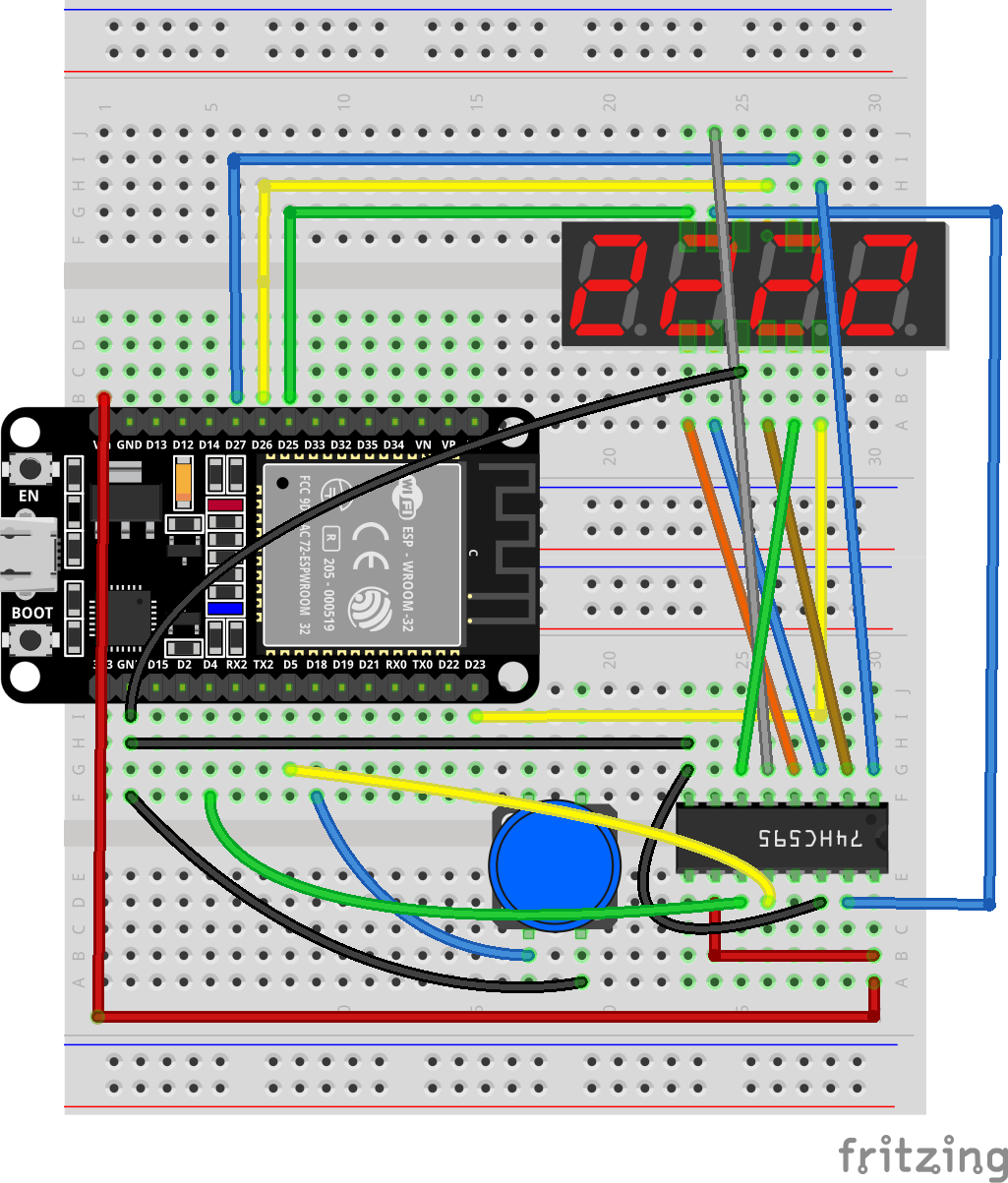
Wiring Table
No. |
Component |
Pin |
Connect to |
|---|---|---|---|
1 |
74HC595 Shift Register |
VCC |
5V |
1 |
74HC595 Shift Register |
GND |
GND |
1 |
74HC595 Shift Register |
MR (Master Reset) |
5V |
1 |
74HC595 Shift Register |
OE (Output Enable) |
GND |
1 |
74HC595 Shift Register |
DS (Data/Serial Input) |
GPIO 15 |
1 |
74HC595 Shift Register |
TCP (Latch/Storage Clock) |
GPIO 5 |
1 |
74HC595 Shift Register |
HCP (Shift Clock) |
GPIO 4 |
2 |
4-Digit 7-Segment Display |
DIGIT 1 (D1) |
GPIO 25 |
2 |
4-Digit 7-Segment Display |
DIGIT 2 (D2) |
GPIO 26 |
2 |
4-Digit 7-Segment Display |
DIGIT 3 (D3) |
GPIO 27 |
2 |
4-Digit 7-Segment Display |
DIGIT 4 (D4) |
GPIO 23 |
2 |
4-Digit 7-Segment Display |
a |
74HC595 Q0 |
2 |
4-Digit 7-Segment Display |
b |
74HC595 Q1 |
2 |
4-Digit 7-Segment Display |
c |
74HC595 Q2 |
2 |
4-Digit 7-Segment Display |
d |
74HC595 Q3 |
2 |
4-Digit 7-Segment Display |
e |
74HC595 Q4 |
2 |
4-Digit 7-Segment Display |
f |
74HC595 Q5 |
2 |
4-Digit 7-Segment Display |
g |
74HC595 Q6 |
2 |
4-Digit 7-Segment Display |
dp (optional) |
74HC595 Q7 |
3 |
Button (Push Switch) |
One pin |
GPIO 18 |
3 |
Button (Push Switch) |
Other pin |
GND |
The schematic diagram is shown below:
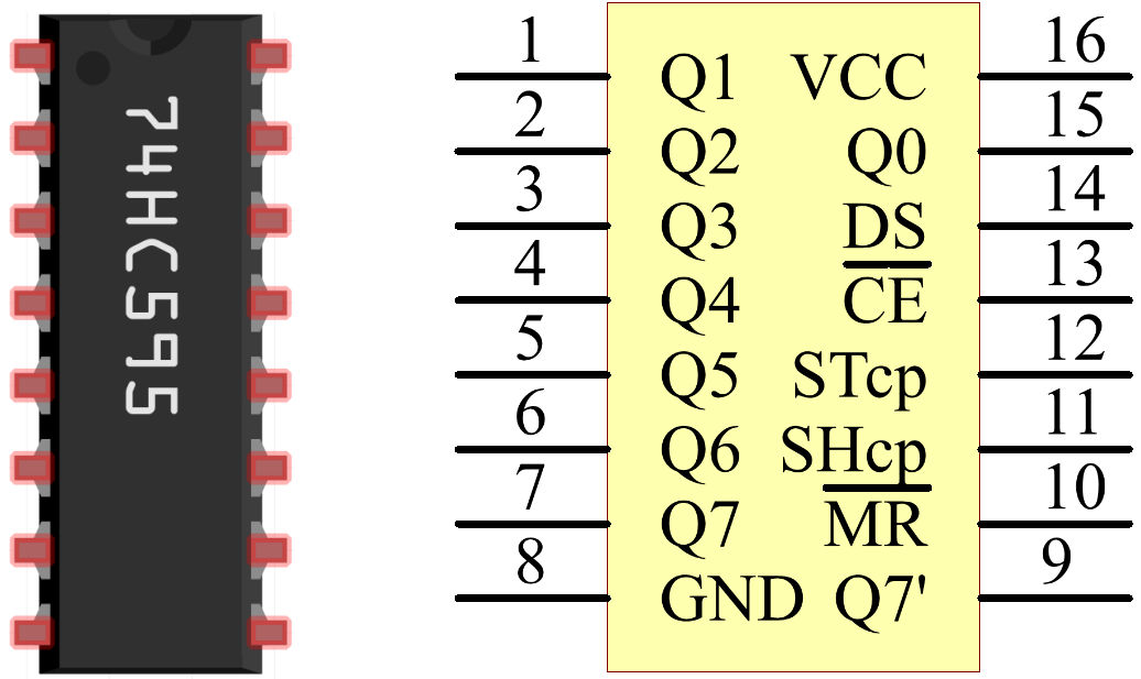
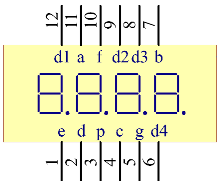
Example code:
Display Effect:
After programming, the 4-digit 7-segment display shows the current count (initially 0000). Each time the button (GPIO18) is pressed, the count increments by 1 and the display updates synchronously, creating a cyclic counter that operates within the 0–9999 range.
14. NTP Clock
This experiment differs little from the previous one; the components used are identical, so there is no need to dismantle the wiring—simply modifying the code is sufficient to display the time using NTP synchronization. You will master the following core skills:
Wi-Fi Connection Management: Use WiFi.begin() to connect to a home router and enable network connectivity for the ESP32.
NTP Time Synchronization: Retrieve UTC time from an NTP server using configTime() and getLocalTime(), then convert it to the local time zone.
Time Data Parsing: Extract hours, minutes, and seconds from the struct tm structure, and split them into tens and units digits for display.
Materials Needed:
ESP32 Development Board
4-7-Segment Display
Breadboard and Jumper Wires
Wiring Diagram:
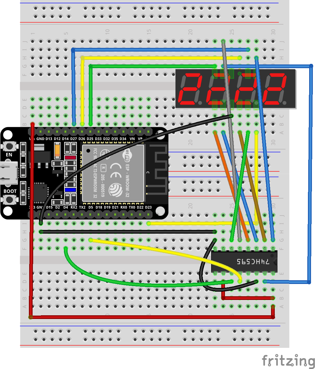
Wiring Table
No. |
Component |
Pin |
Connect to |
|---|---|---|---|
1 |
74HC595 Shift Register |
VCC |
5V(VIN) |
1 |
74HC595 Shift Register |
GND |
GND |
1 |
74HC595 Shift Register |
MR (Master Reset) |
5V(VIN) |
1 |
74HC595 Shift Register |
OE (Output Enable) |
GND |
1 |
74HC595 Shift Register |
DS (Data/Serial Input) |
GPIO 15 |
1 |
74HC595 Shift Register |
TCP (Latch/Storage Clock) |
GPIO 5 |
1 |
74HC595 Shift Register |
HCP (Shift Clock) |
GPIO 4 |
2 |
4-Digit 7-Segment Display |
DIGIT 1 (D1) |
GPIO 25 |
2 |
4-Digit 7-Segment Display |
DIGIT 2 (D2) |
GPIO 26 |
2 |
4-Digit 7-Segment Display |
DIGIT 3 (D3) |
GPIO 27 |
2 |
4-Digit 7-Segment Display |
DIGIT 4 (D4) |
GPIO 23 |
2 |
4-Digit 7-Segment Display |
a |
74HC595 Q0 |
2 |
4-Digit 7-Segment Display |
b |
74HC595 Q1 |
2 |
4-Digit 7-Segment Display |
c |
74HC595 Q2 |
2 |
4-Digit 7-Segment Display |
d |
74HC595 Q3 |
2 |
4-Digit 7-Segment Display |
e |
74HC595 Q4 |
2 |
4-Digit 7-Segment Display |
f |
74HC595 Q5 |
2 |
4-Digit 7-Segment Display |
g |
74HC595 Q6 |
2 |
4-Digit 7-Segment Display |
dp (optional) |
74HC595 Q7 |
Example code:
Code modification
Please first update the Wi-Fi information in the code to a network you can connect to; otherwise, the device will be unable to connect to the internet for time synchronization.
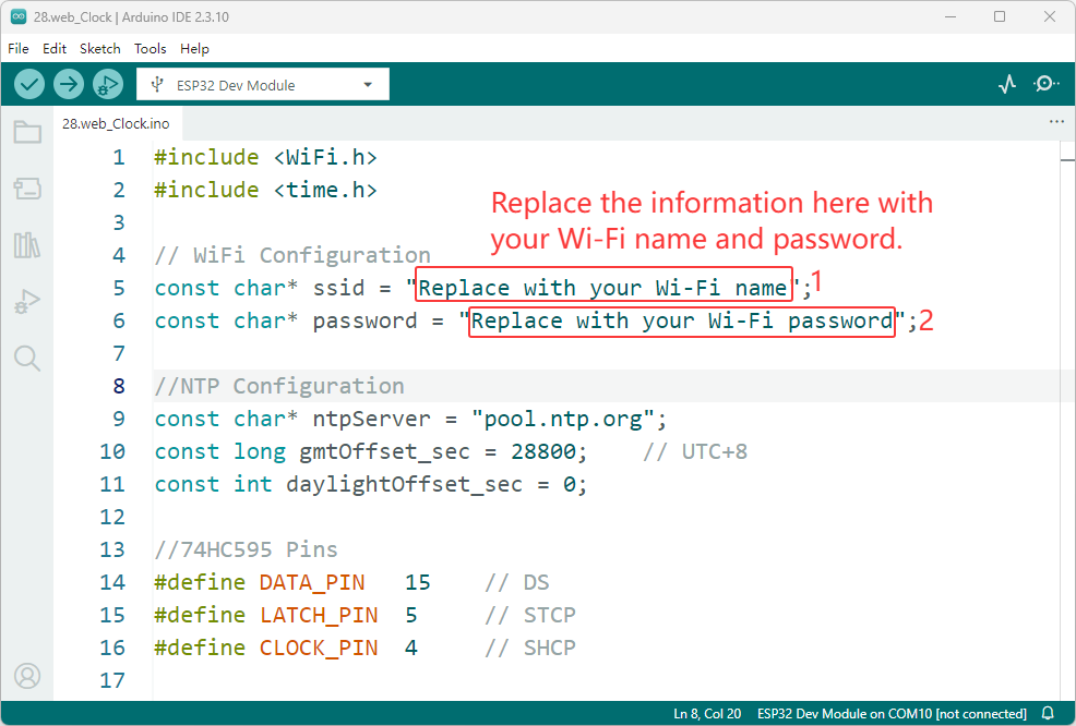
To display the real-time time for your country or region, please replace the UTC time in the code with your local time zone.
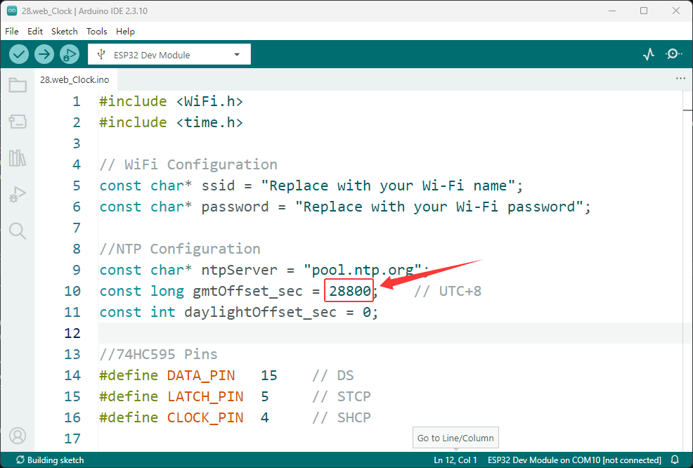
This table lists common countries and their UTC offsets for easy reference:
Country / Region |
Time Zone |
UTC Offset |
Offset (Seconds) |
|---|---|---|---|
China |
CST (China Standard Time) |
UTC+8 |
28800 |
Japan |
JST (Japan Standard Time) |
UTC+9 |
32400 |
South Korea |
KST (Korea Standard Time) |
UTC+9 |
32400 |
Singapore |
SGT (Singapore Time) |
UTC+8 |
28800 |
Malaysia |
MYT (Malaysia Time) |
UTC+8 |
28800 |
Philippines |
PHT (Philippine Time) |
UTC+8 |
28800 |
India |
IST (India Standard Time) |
UTC+5:30 |
19800 |
Thailand |
ICT (Indochina Time) |
UTC+7 |
25200 |
Vietnam |
ICT (Indochina Time) |
UTC+7 |
25200 |
Indonesia (Jakarta) |
WIB (Western Indonesia Time) |
UTC+7 |
25200 |
Australia (Sydney) |
AEST (Australian Eastern Standard Time) |
UTC+10 |
36000 |
Australia (Perth) |
AWST (Australian Western Standard Time) |
UTC+8 |
28800 |
New Zealand |
NZST (New Zealand Standard Time) |
UTC+12 |
43200 |
United Kingdom |
GMT (Greenwich Mean Time) |
UTC+0 |
0 |
France |
CET (Central European Time) |
UTC+1 |
3600 |
Germany |
CET (Central European Time) |
UTC+1 |
3600 |
Italy |
CET (Central European Time) |
UTC+1 |
3600 |
Spain |
CET (Central European Time) |
UTC+1 |
3600 |
Greece |
EET (Eastern European Time) |
UTC+2 |
7200 |
Turkey |
TRT (Turkey Time) |
UTC+3 |
10800 |
Russia (Moscow) |
MSK (Moscow Time) |
UTC+3 |
10800 |
United States (New York) |
EST (Eastern Standard Time) |
UTC-5 |
-18000 |
United States (Chicago) |
CST (Central Standard Time) |
UTC-6 |
-21600 |
United States (Denver) |
MST (Mountain Standard Time) |
UTC-7 |
-25200 |
United States (Los Angeles) |
PST (Pacific Standard Time) |
UTC-8 |
-28800 |
Canada (Toronto) |
EST (Eastern Standard Time) |
UTC-5 |
-18000 |
Canada (Vancouver) |
PST (Pacific Standard Time) |
UTC-8 |
-28800 |
Mexico |
CST (Central Standard Time) |
UTC-6 |
-21600 |
Brazil (Sao Paulo) |
BRT (Brasilia Time) |
UTC-3 |
-10800 |
Argentina |
ART (Argentina Time) |
UTC-3 |
-10800 |
South Africa |
SAST (South Africa Standard Time) |
UTC+2 |
7200 |
Egypt |
EET (Eastern European Time) |
UTC+2 |
7200 |
UAE (Dubai) |
GST (Gulf Standard Time) |
UTC+4 |
14400 |
Saudi Arabia |
AST (Arabia Standard Time) |
UTC+3 |
10800 |
Israel |
IST (Israel Standard Time) |
UTC+2 |
7200 |
Afghanistan |
AFT (Afghanistan Time) |
UTC+4:30 |
16200 |
Nepal |
NPT (Nepal Time) |
UTC+5:45 |
20700 |
Myanmar |
MMT (Myanmar Time) |
UTC+6:30 |
23400 |
Sri Lanka |
SLST (Sri Lanka Standard Time) |
UTC+5:30 |
19800 |
Pakistan |
PKT (Pakistan Standard Time) |
UTC+5 |
18000 |
Bangladesh |
BST (Bangladesh Standard Time) |
UTC+6 |
21600 |
Ukraine |
EET (Eastern European Time) |
UTC+2 |
7200 |
Portugal |
WET (Western European Time) |
UTC+0 |
0 |
Netherlands |
CET (Central European Time) |
UTC+1 |
3600 |
Switzerland |
CET (Central European Time) |
UTC+1 |
3600 |
Sweden |
CET (Central European Time) |
UTC+1 |
3600 |
Norway |
CET (Central European Time) |
UTC+1 |
3600 |
Finland |
EET (Eastern European Time) |
UTC+2 |
7200 |
Ireland |
GMT (Greenwich Mean Time) |
UTC+0 |
0 |
Iceland |
GMT (Greenwich Mean Time) |
UTC+0 |
0 |
Kenya |
EAT (East Africa Time) |
UTC+3 |
10800 |
Nigeria |
WAT (West Africa Time) |
UTC+1 |
3600 |
Morocco |
WET (Western European Time) |
UTC+0 |
0 |
Argentina |
ART (Argentina Time) |
UTC-3 |
-10800 |
Chile |
CLT (Chile Standard Time) |
UTC-3 |
-10800 |
Colombia |
COT (Colombia Time) |
UTC-5 |
-18000 |
Peru |
PET (Peru Time) |
UTC-5 |
-18000 |
Venezuela |
VET (Venezuela Time) |
UTC-4 |
-14400 |
Click here to look up UTC times for other regions. UTC Time Lookup
Display Effect:
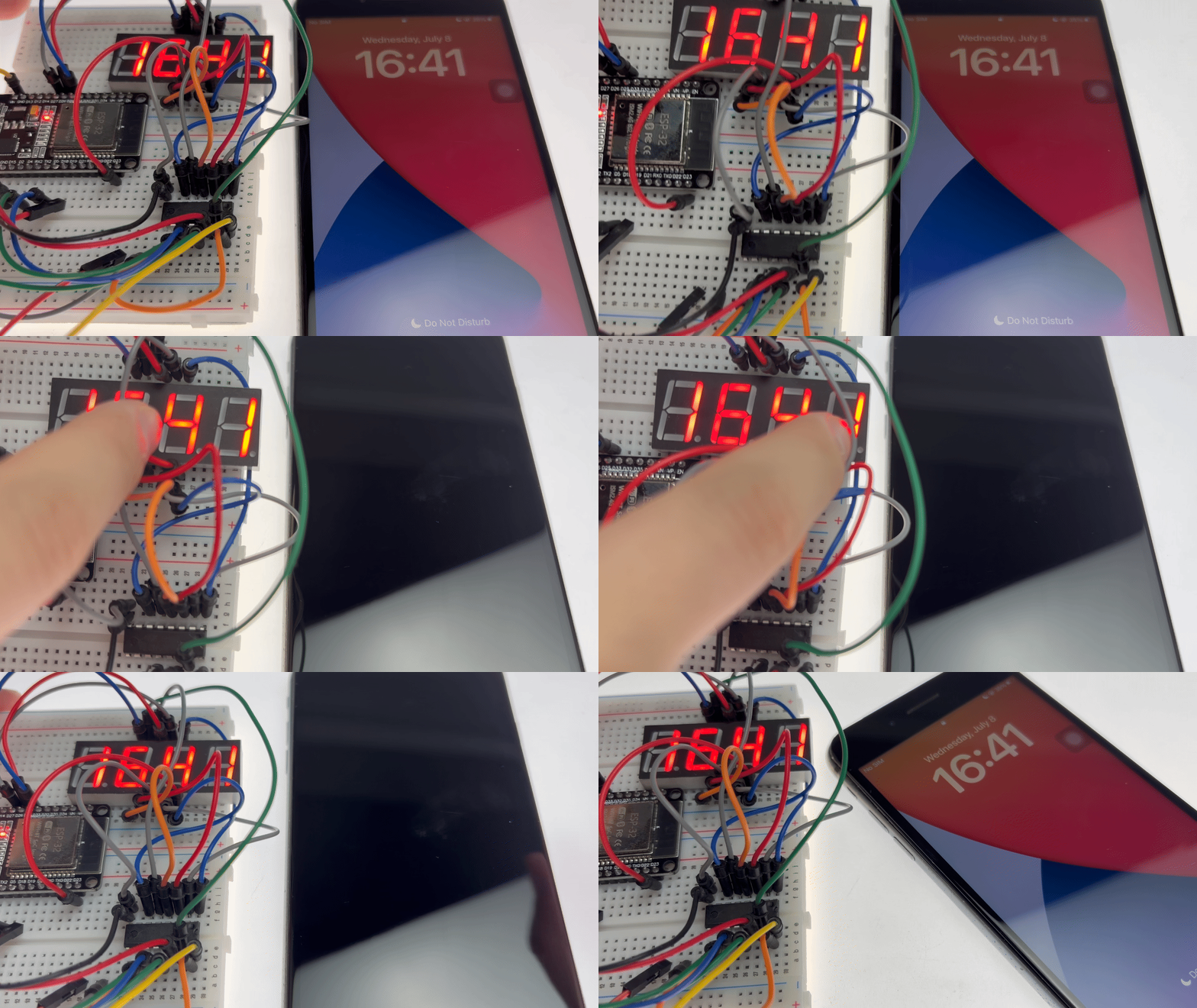
After the program is flashed, the ESP32 automatically connects to the specified Wi-Fi network and requests the current time from an NTP server upon a successful connection. Once the time is retrieved, a 4-digit digital display shows the current time in real-time using the “HH:MM” (hours:minutes) format.
15. Simple Level
This experiment is a comprehensive project covering sensor fusion and attitude estimation. It aims to teach you how to use the MPU6050 6-axis Inertial Measurement Unit (IMU) to acquire acceleration and angular velocity data, calculate the device’s tilt angles (Roll and Pitch) using a complementary filter algorithm, and display a dynamic level indicator in real-time on an OLED screen. You will master the following core skills:
MPU6050 Sensor Driver: Reading accelerometer and gyroscope data via the Adafruit_MPU6050 library and understanding the physical principles behind measuring gravity components (accelerometer) and angular velocity (gyroscope).
Attitude Estimation Algorithms: Calculating static tilt angles from accelerometer data using atan2() and determining dynamic angular changes by integrating gyroscope angular velocity.
Complementary Filter Fusion: Fusing data from the accelerometer (accurate at low frequencies but noisy) and the gyroscope (fast high-frequency response but prone to drift) using a weighting coefficient (alpha=0.92) to achieve stable, responsive attitude estimation.
Sensor Bandwidth Configuration: Setting the MPU6050 filter bandwidth to 260Hz to increase the data update rate and capture rapid movements.
Real-time Graphics Rendering: Drawing crosshairs, a dynamic bubble indicator, angle values, and a bar-style level indicator on the OLED screen to provide intuitive visual feedback.
Microsecond-level Timing: Using micros() to precisely calculate sampling intervals, thereby improving integration precision and the accuracy of the attitude estimation.
Materials Needed:
ESP32 Development Board
MPU6050 Attitude Sensor
0.96-inch OLED Display
Breadboard and Jumper Wires
Wiring Diagram:
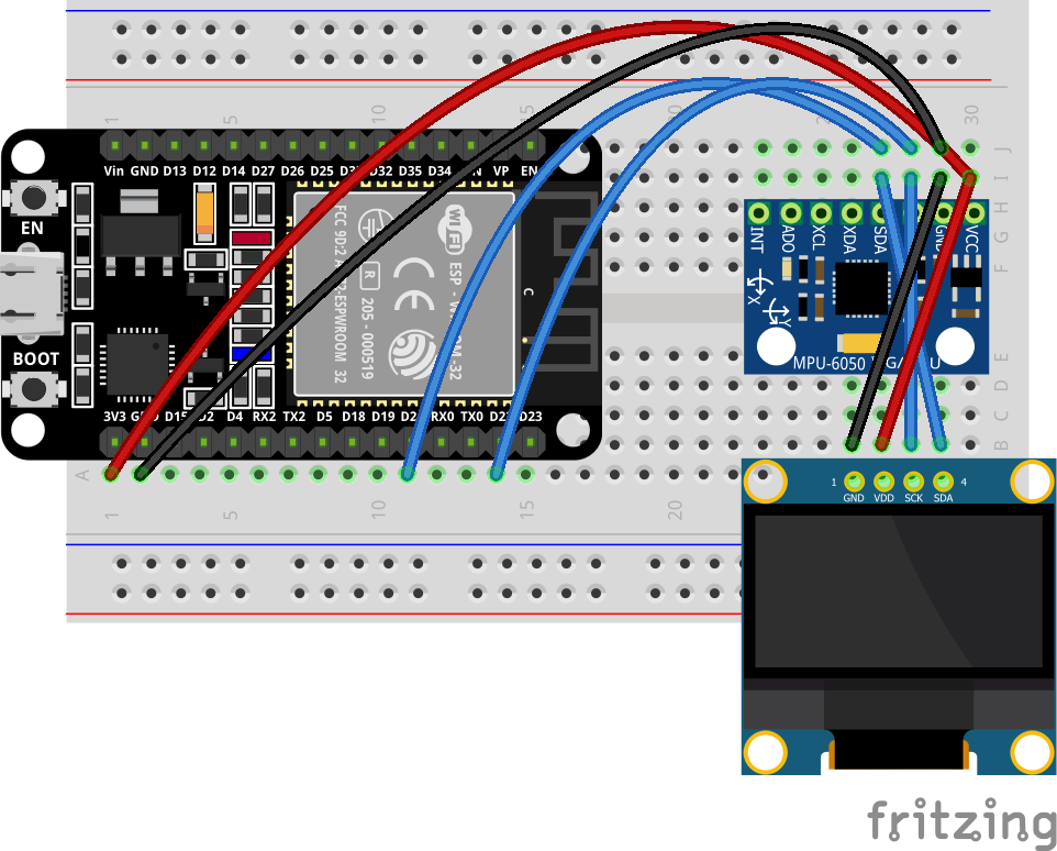
Wiring Table
No. |
Component |
Pin |
Connect to |
|---|---|---|---|
1 |
MPU6050 |
VCC |
3.3V |
1 |
MPU6050 |
GND |
GND |
1 |
MPU6050 |
SCL |
GPIO 22 |
1 |
MPU6050 |
SDA |
GPIO 21 |
2 |
0.96 OLED |
VCC |
3.3V |
2 |
0.96 OLED |
GND |
GND |
2 |
0.96 OLED |
SCL |
GPIO 22 |
2 |
0.96 OLED |
SDA |
GPIO 21 |
Example code:
Display Effect:
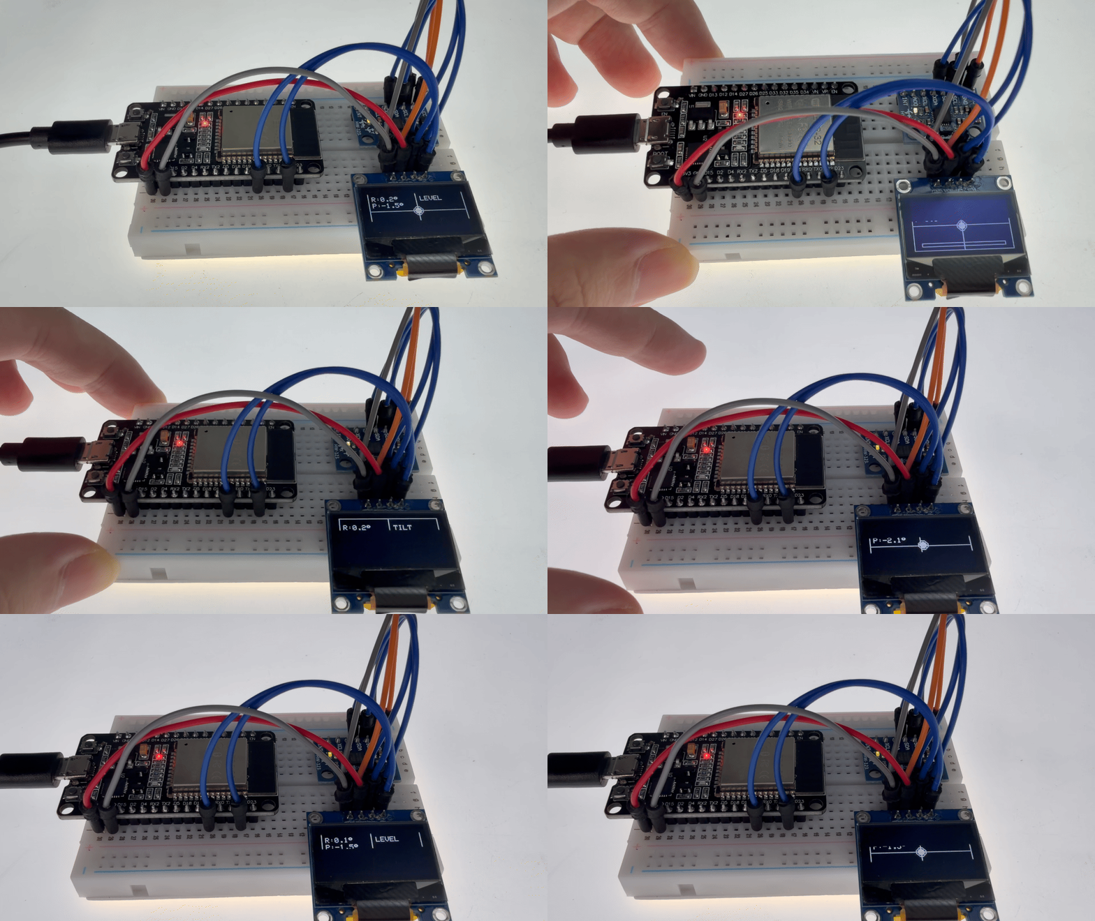
After flashing the program, the OLED screen displays a comprehensive digital level interface:
Crosshair reference lines: Fixed at the center of the screen to serve as a horizontal baseline.
Dynamic bubble: Moves in response to device tilt, simulating the behavior of a bubble in a real spirit level.
Angle readings: Real-time display of Roll and Pitch angles with 0.1° precision.
Level status indicator: Displays “LEVEL” when the absolute values of both angles are less than 2°; otherwise, displays “TILT”.
Bar-style level indicator: A bar graph at the bottom of the screen visually represents the degree of left-right tilt.
When the device is tilted, the bubble moves smoothly in the direction of the tilt, the angle readings update synchronously, and the bar graph adjusts accordingly, mimicking the behavior of a real physical level.
16. Variable Speed Fan
This experiment is a comprehensive project combining PWM-based motor speed control with push-button input. It aims to teach you how to use an ESP32 to control the speed of a DC motor via PWM signals and to cycle through speed levels using a push-button. You will master the following core skills:
PWM Speed Control: Configuring the ESP32’s PWM channels (5 kHz frequency, 8-bit resolution) using ledcAttach() and ledcWrite() to achieve continuous (stepless) motor speed adjustment across a range of 0–255.
L298N Motor Driver Module: Controlling motor direction (forward/reverse) via the IN1 and IN2 pins, and regulating speed by applying the PWM signal to the ENA (enable) pin.
Cyclic Speed Control Logic: Using a push-button to cycle through speed modes—“Off → Low → Medium → High → Off”—while outputting the current speed level status via the serial monitor.
State Machine Management: Managing the current speed level using a variable (speedLevel, ranging from 0 to 3), where each level corresponds to a specific PWM duty cycle.
Materials Needed:
ESP32 Development Board
Motor Module
L293D
Button
Power Supply Board
Breadboard and Jumper Wires
Wiring Diagram:
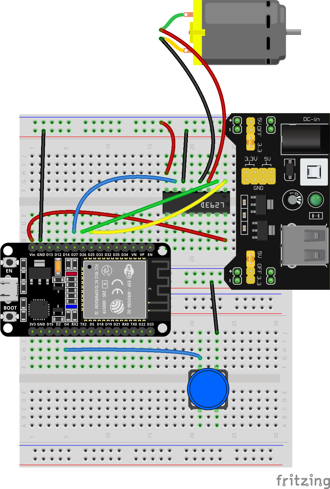
Wiring Table
No. |
Component |
Pin |
Connect to |
|---|---|---|---|
1 |
L293D |
VCC(VSS) |
5V |
1 |
L293D |
GND |
GND |
1 |
L293D |
ENA |
GPIO 25 |
1 |
L293D |
IN1 |
GPIO 26 |
1 |
L293D |
IN2 |
GPIO 27 |
2 |
DC Motor |
Positive (+) |
L293D OUT1 |
2 |
DC Motor |
Negative (-) |
L293D OUT2 |
3 |
Button |
One pin |
GPIO 4 |
3 |
Button |
Other pin |
GND |
4 |
External Power Supply |
Positive (+) |
L293D VS |
4 |
External Power Supply |
Negative (-) |
L293D GND |
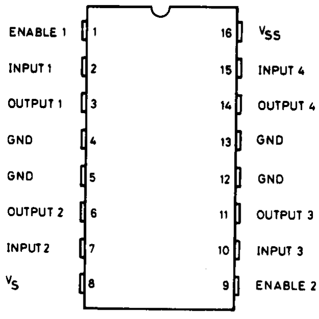
The L293D pinout diagram is shown below:
Example code:
Display Effect:
After the program is flashed, the system enters standby mode. Each short press of the button (GPIO4) cycles the motor speed through the sequence: Off → Low → Medium → High → Off. The serial monitor simultaneously outputs the current speed level, facilitating debugging and observation.
17. Stepper Motor Drive And Control
This experiment serves as an introductory project for stepper motor driving and control, designed to teach you how to use an ESP32 to drive a 28BYJ-48 stepper motor and achieve precise angular control for both clockwise and counter-clockwise rotation. You will master the following core skills:
Stepper motor operating principles: Understand how the motor uses pulse signals to rotate the rotor in discrete steps and grasp the relationship between the step angle and the number of pulses.
Using the Stepper library: Simplify motor control using the `Stepper.h` library, specifically mastering `setSpeed()` to configure rotation speed and `step()` to send pulses.
28BYJ-48 gear reduction parameters: Understand that this model operates at 2,048 steps per revolution in single-step mode (due to a 1:64 gear reduction ratio, resulting in approximately 0.175° per step) and how different driving modes affect the step count.
Pin configuration: Master the mapping between the 28BYJ-48’s four-phase windings and the driver pins (IN1→IN3→IN2→IN4) to ensure proper motor operation.
Forward and reverse control: Control the direction of rotation using positive and negative step values (positive for clockwise, negative for counter-clockwise).
Materials Needed:
ESP32 Development Board
28BYJ-48 Stepper Motor
ULN2003 Motor Driver
Power Supply Board
Breadboard and Jumper Wires
Wiring Diagram:
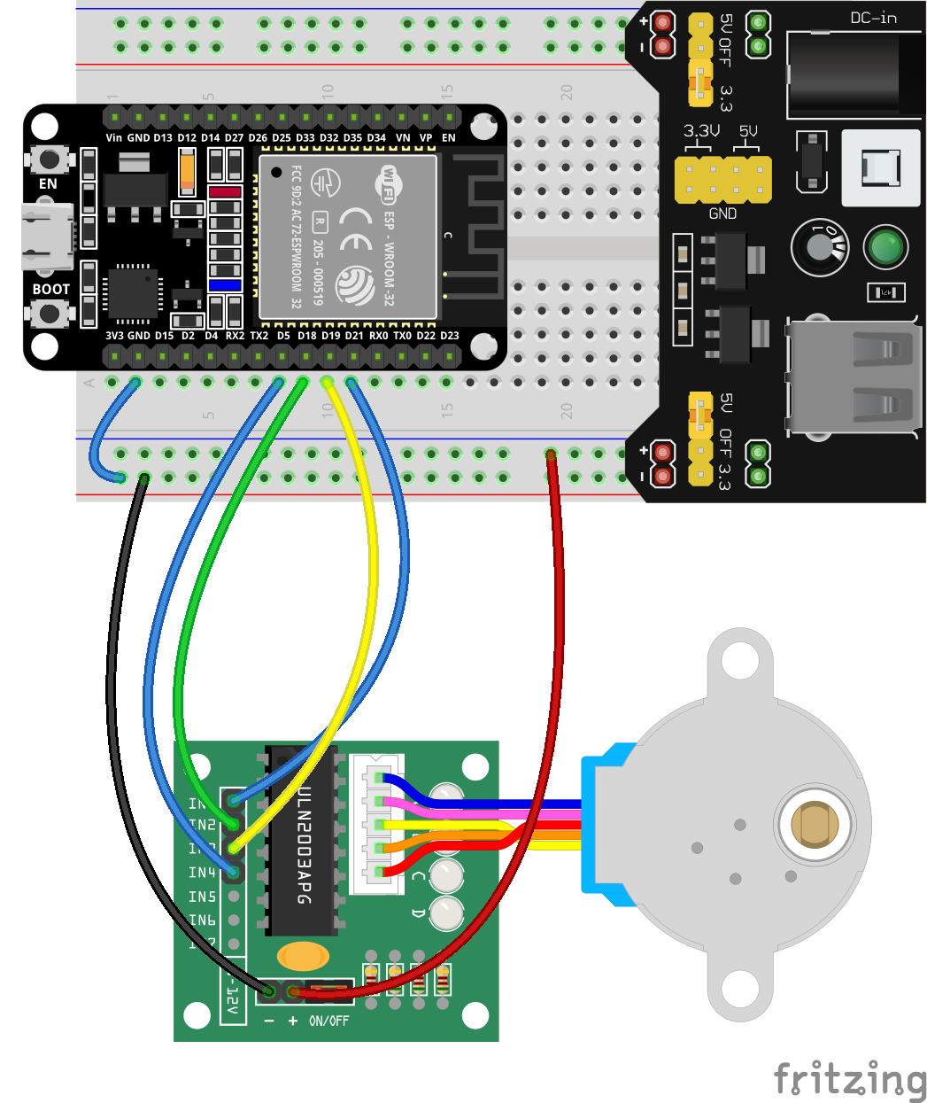
Wiring Table
No. |
Component |
Pin |
Connect to |
|---|---|---|---|
1 |
ULN2003 Stepper Driver |
VCC |
5V |
1 |
ULN2003 Stepper Driver |
GND |
GND |
1 |
ULN2003 Stepper Driver |
IN1 |
GPIO 21 |
1 |
ULN2003 Stepper Driver |
IN2 |
GPIO 19 |
1 |
ULN2003 Stepper Driver |
IN3 |
GPIO 18 |
1 |
ULN2003 Stepper Driver |
IN4 |
GPIO 5 |
Example code:
#include <Stepper.h>
// 28BYJ-48 parameters
const int stepsPerRevolution = 2048;  // Single-step mode: 2048 steps/revolution
const int rolePerMinute = 15;         // Speed (RPM), recommended 10-15, max ~17
Stepper myStepper(stepsPerRevolution, 21, 19, 18, 5);  // Sequence: IN1, IN3, IN2, IN4
void setup() {
  myStepper.setSpeed(rolePerMinute);
}
void loop() {
  // Rotate one revolution clockwise
  myStepper.step(stepsPerRevolution);
  delay(1000);  // Pause 1 second

  // Rotate one revolution counterclockwise
  myStepper.step(-stepsPerRevolution);
  delay(1000);
}
Display Effect:
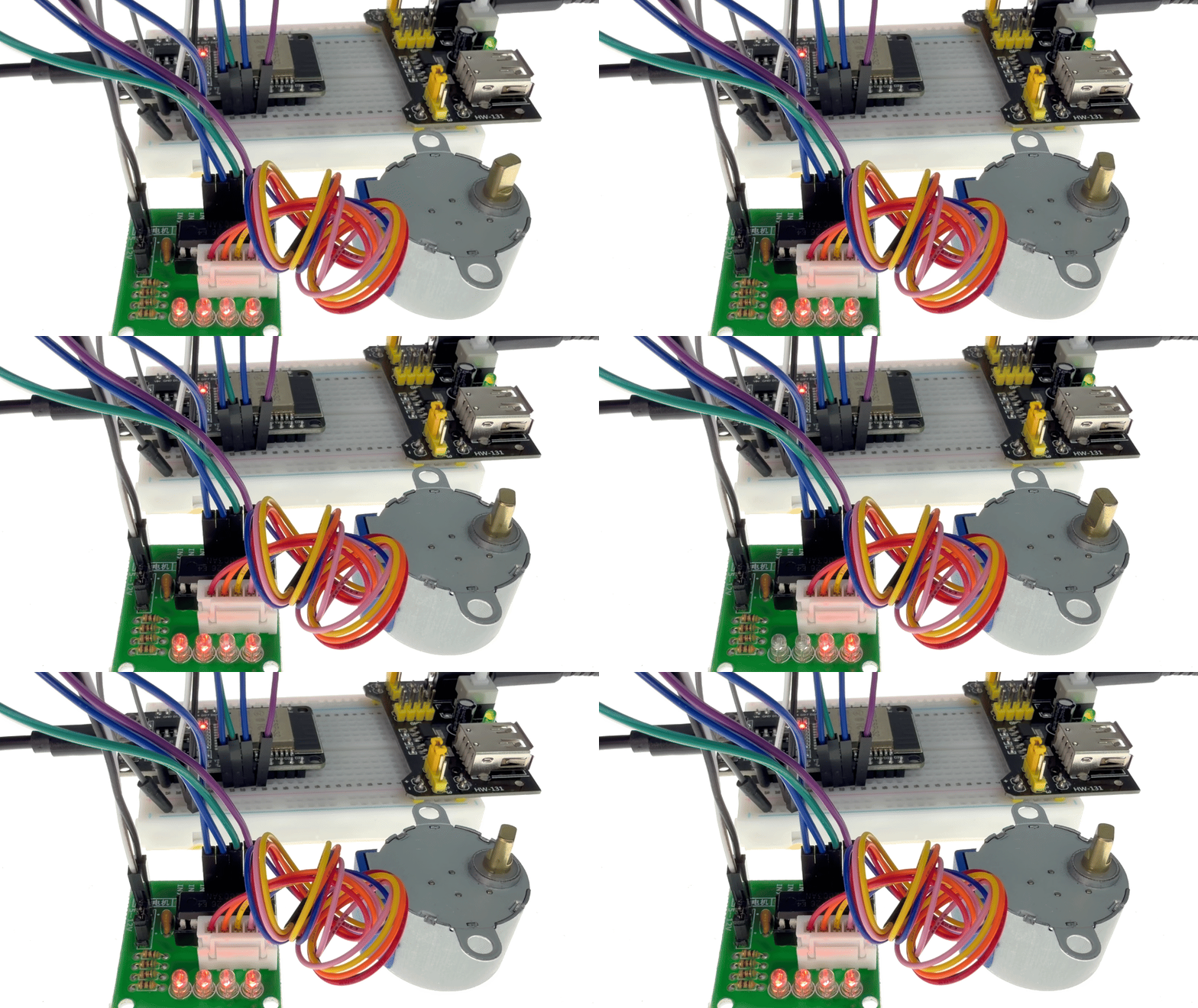
After the program is uploaded, the stepper motor rotates one full revolution (2,048 steps) clockwise at 15 RPM, pauses for one second, then rotates one full revolution counter-clockwise and pauses for another second; this cycle repeats, creating a reciprocating rotation demonstration.
18. RFID Door Lock System
This experiment is a comprehensive project involving an RFID access control system. It aims to teach the integration of RFID card recognition with servo motor control to create a smart access system that unlocks upon card scanning and automatically resets. You will master the following core skills:
RFID Card ID Reading: Reading the UID of ISO14443A-compliant RFID cards/tags using the MFRC522 module and understanding the principles of contactless near-field communication.
Custom SPI Pin Configuration: Using SPI.begin(SCK, MISO, MOSI, SS) to customize bus pins, allowing for flexible adaptation to different development boards.
ESP32 Servo Control: Controlling the servo motor’s rotation angle via PWM signals to operate the door lock mechanism.
Non-blocking Timer Design: Using millis() to trigger an automatic reset (locking the door) three seconds after opening, thereby avoiding the use of delay() which would block the main loop.
Serial Status Logging: Printing real-time logs of card detection, UID information, servo actions, and system status to facilitate debugging and monitoring.
Materials Needed:
ESP32 Development Board
MFRC522 RFID Module
SG90 Servo
Power Supply Board
Breadboard and Jumper Wires
Wiring Diagram:
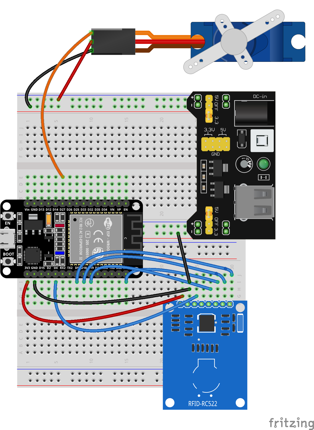
Wiring Table
No. |
Component |
Pin |
Connect to |
|---|---|---|---|
1 |
RC522 RFID Module |
VCC |
3.3V |
1 |
RC522 RFID Module |
GND |
GND |
1 |
RC522 RFID Module |
RST |
GPIO 4 |
1 |
RC522 RFID Module |
SDA (SS) |
GPIO 5 |
1 |
RC522 RFID Module |
MOSI |
GPIO 23 |
1 |
RC522 RFID Module |
MISO |
GPIO 19 |
1 |
RC522 RFID Module |
SCK |
GPIO 18 |
2 |
SG90 Servo |
Red (VCC) |
5V |
2 |
SG90 Servo |
Brown (GND) |
GND |
2 |
SG90 Servo |
Orange (Signal) |
GPIO 27 |
Example code:
Display Effect:
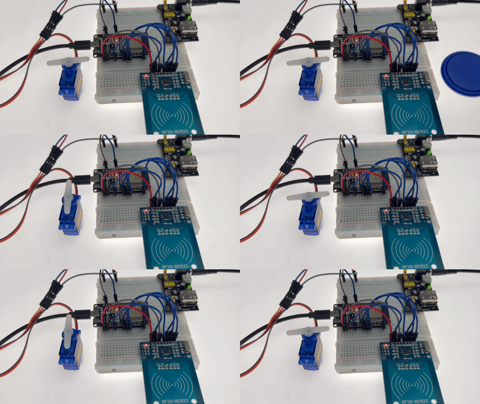
After the program is uploaded, the system enters standby mode, and the servo holds its position at 0° (door closed).
When any RFID card or tag is brought near the reader, the serial port outputs the card’s full UID (in hexadecimal format), and the servo immediately rotates to 90° (door open), while the serial port displays the message “Door opened.”
After 3 seconds, the servo automatically returns to 0° (door closed), and the system reverts to standby mode, awaiting the next card scan. This sequence completes the full automated access control process: “scan card → open door → delay → close door.”
19. Mini Game: Snake
This experiment is a comprehensive embedded game development project designed to teach you how to use an ESP32 to drive an OLED display, a joystick, and a buzzer to implement the classic “Snake” game. You will master the following core skills:
Game State Machine Management: Managing state transitions—“Title Screen” → “In-Game” → “Game Over”—using a GameState enumeration.
Joystick Direction Control: Reading ADC values to determine joystick X/Y-axis movement, implementing dead-zone logic to prevent accidental inputs, and ensuring smooth directional control.
Snake Body Data Structure: Storing body coordinates in an array, implementing movement logic via “head-insertion” (shifting elements), and supporting dynamic body length expansion.
Collision Detection & Food Generation: Detecting whether the snake’s head consumes food or collides with walls or its own body, and generating new food at random, valid locations.
Dynamic Difficulty System: Gradually increasing the snake’s movement speed as the score rises (reducing moveDelay from 200ms to 80ms).
Audio Feedback: Playing a short, high-frequency tone (1200Hz, 80ms) when consuming food, and a descending tone sequence (800Hz → 100Hz) upon “Game Over” to enhance immersion.
Materials Needed:
ESP32 Development Board
0.96-inch OLED Display
Joystick Module
Passive Buzzer
Breadboard and Jumper Wires
Wiring Diagram:
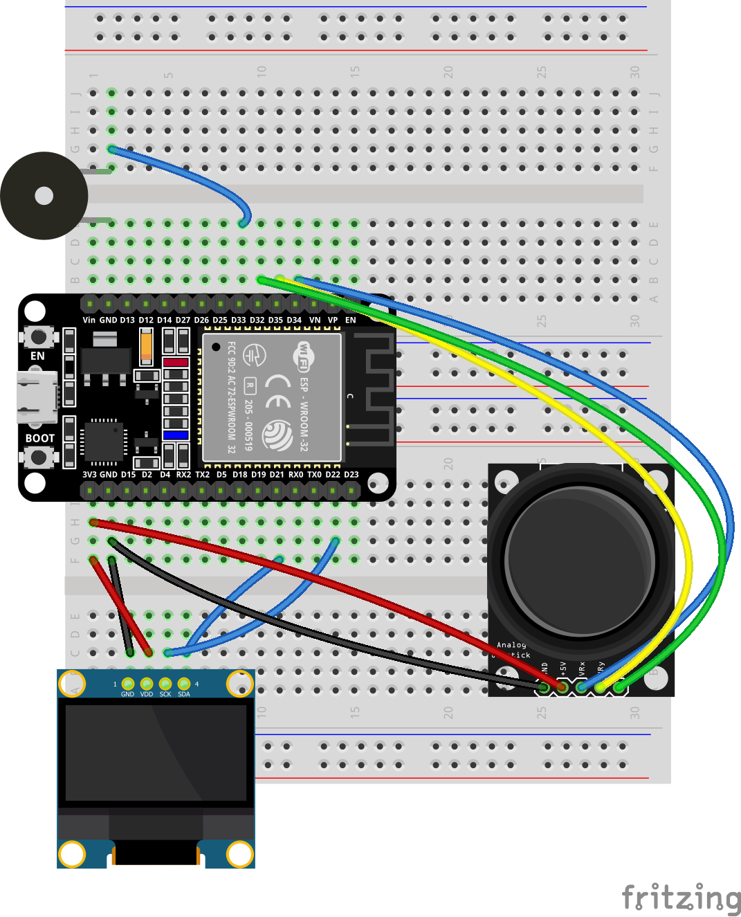
Wiring Table
No. |
Component |
Pin |
Connect to |
|---|---|---|---|
1 |
0.96 OLED |
VCC |
3.3V |
1 |
0.96 OLED |
GND |
GND |
1 |
0.96 OLED |
SCL |
GPIO 22 |
1 |
0.96 OLED |
SDA |
GPIO 21 |
2 |
Joystick Module |
VCC |
3.3V |
2 |
Joystick Module |
GND |
GND |
2 |
Joystick Module |
VRX (X-axis) |
GPIO 34 |
2 |
Joystick Module |
VRY (Y-axis) |
GPIO 35 |
2 |
Joystick Module |
SW (Button) |
GPIO 32 |
3 |
Passive Buzzer |
Positive (+) |
GPIO 33 |
3 |
Passive Buzzer |
Negative (-) |
GND |
Example code:
Display Effect:
After flashing the program, the OLED screen displays the title page, showing the game name, a “PRESS TO START” prompt, and the current high score. Press the joystick button to start the game:
Joystick controls: Move the joystick up, down, left, or right to control the snake’s direction; the snake wraps around the screen edges (passing from one side to the other).
Scoring by eating: When the snake’s head touches the food, its body grows by one segment, the score increases by 1, and the buzzer emits a short, high-pitched tone.
Increasing speed: The snake’s movement speed gradually increases with each piece of food consumed; at maximum difficulty, the movement interval drops to 80ms.
Game Over: The game ends if the snake’s head collides with its own body; “GAME OVER” and the current score are displayed, and the buzzer plays a “game over” sound effect.
Restart: Press the joystick button again to return to the title page, then press any directional input or the button to start a new game.
20. Weather Desk
This experiment involves an integrated environmental monitoring and intelligent alarm system. It aims to teach you how to collect environmental data using a DHT11 temperature and humidity sensor and a photosensitive sensor, display this data in real-time on an OLED screen, and trigger a buzzer alarm based on environmental conditions. You will master the following core skills:
Multi-sensor data acquisition: Simultaneously reading DHT11 temperature and humidity data (every 2 seconds) and digital signals from the photosensitive sensor to achieve multi-dimensional environmental sensing.
OLED information display: Displaying temperature, humidity, lighting status, and alarm information in designated zones on a 128×64 OLED screen for clear data visualization.
Combined alarm logic: Automatically triggering a buzzer alarm when ambient light is too low (nighttime or obstruction) or the temperature exceeds 40°C, implementing an intelligent “OR” logic warning system.
Non-blocking timed sampling: Using millis() to perform timed data acquisition and display updates every 2 seconds, avoiding the use of delay() which would block the main loop.
Status feedback and debugging: Synchronously outputting sensor data, lighting status, and alarm trigger reasons via the serial port to facilitate system debugging and status monitoring.
Materials Needed:
ESP32 Development Board
0.96-inch OLED Display
DHT11 Sensor
Light Sensor
Active Buzzer
Breadboard and Jumper Wires
Wiring Diagram:
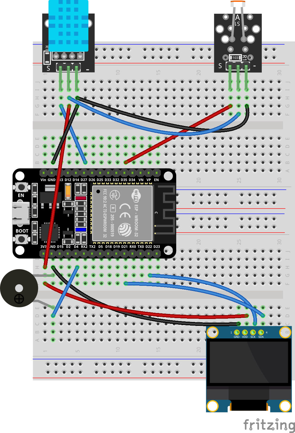
Wiring Table
No. |
Component |
Pin |
Connect to |
|---|---|---|---|
1 |
0.96 OLED |
VCC |
3.3V |
1 |
0.96 OLED |
GND |
GND |
1 |
0.96 OLED |
SCL |
GPIO 22 |
1 |
0.96 OLED |
SDA |
GPIO 21 |
2 |
DHT11 Sensor |
VCC |
3.3V |
2 |
DHT11 Sensor |
GND |
GND |
2 |
DHT11 Sensor |
DATA |
GPIO 27 |
3 |
Light Sensor |
VCC |
3.3V |
3 |
Light Sensor |
GND |
GND |
3 |
Light Sensor |
DO |
GPIO 35 |
4 |
Active Buzzer |
Positive (+) |
GPIO 4 |
4 |
Active Buzzer |
Negative (-) |
GND |
Example code:
Display Effect:
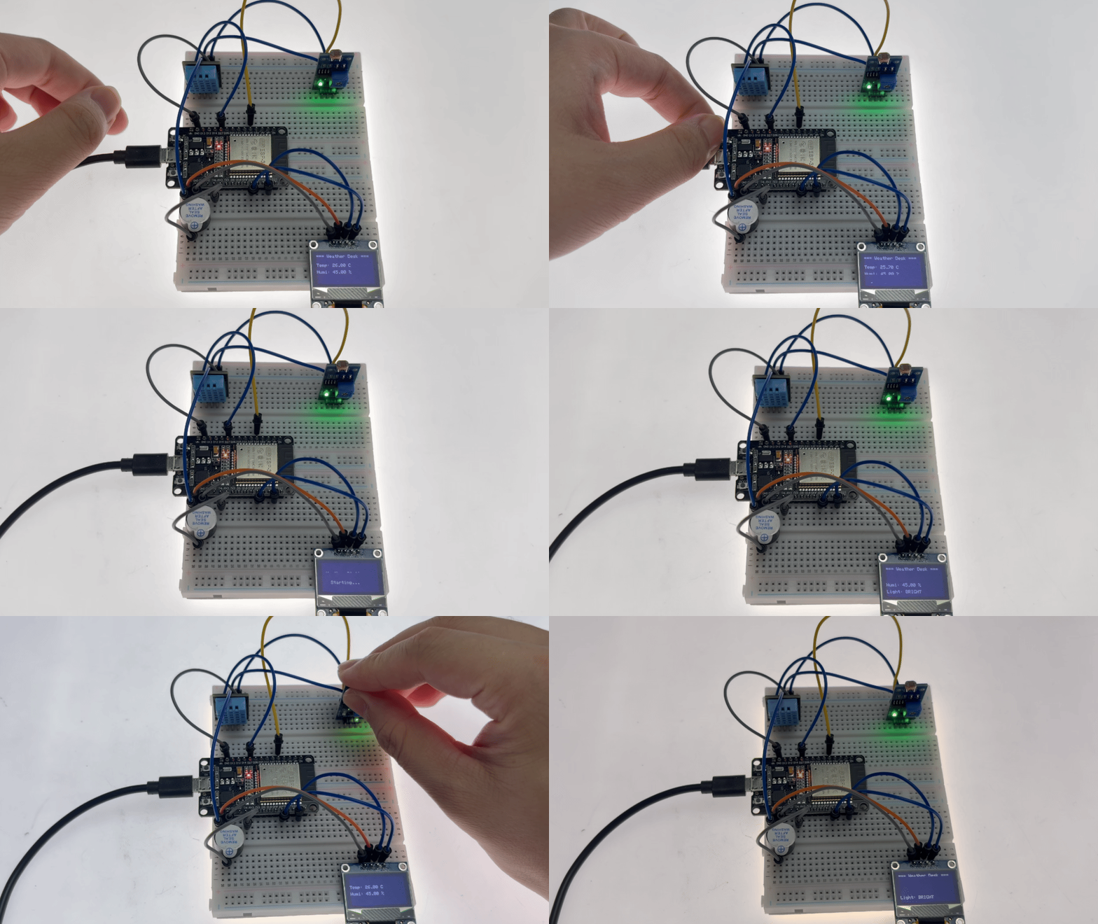
After the program is flashed, the OLED screen displays the startup screen before entering the main interface, where temperature, humidity, and light status are displayed in real-time and updated every 2 seconds.
When the ambient light dims (causing the photosensitive sensor to output a high level) or the temperature exceeds 40°C, the buzzer immediately sounds an alarm; the OLED light status indicator displays “DARK,” and the serial port outputs the cause of the alarm (“Dark,” “Overheat,” or both).
When the light brightens and the temperature drops below 40°C, the buzzer automatically turns off, and the system returns to its normal state.